


THE GAS EXHIBITION.
Page 19
Page 20
If you've noticed an error in this article please click here to report it so we can fix it.
Forecast of the Exhibits. New and Interesting Installations.
At the British Scientific Products Exhibition, which opens at King's College, Strand, on the 12th of this month, a section which will be found to be of considerable interest to our readers is being devoted to gas-traction matters. We have prepared in the following two pages a forecast of the exhibits, which. will be found to contain some new and interesting apparatus necessary in the conversion of vehicles to run on gas.
New Semi-rigid Container.
Interest will be centred in the design of a high-compression gas cylinder Which will be shown by Stela-stie Tyres Ltd. It departure, entirely a new departe, so far as we know, from anything which has been tried and tested up to the present, and from first examination it would appear
to possess features e to overcome Biome of the retarding difficulties which are known to exist in other types particularly in respect to weight.
. It takes the form of finely-drawn but stout steel netting, the mesh of which is close-grained. This is utilized for the outer casing within -which is situated a rubber container somewhat resembling the inner tube of a bicycle. The outer casing is weaved in one piece. so that thee is no join throughout the whole length of the cylinder. In securing the end of the cylinders into which the gas is drawn, the steel netting is drawn up together, and a number of V-shaped lead wedges are driven in to make the end secure. It has been found in the course of extensive tests which have been carried out at the works of the company that the pressure of the gas drives the meshing of the outer caging into these wedges, which are made of a comparatively soft metal ; in fact, it cuts into the lead, thus counteracting whatever tendency may exist for the wedges to blow out. It is intended that the cylinder should be used up to a pressure of 300—it has stood more than 900 on test—and if a greater pressure than 1000 is needed the company intends employing a reinforcing netting to go inside the present outer caeieg. We illustrate the two meshes on this page.. The complete apparatus only si eigh.s 27 lb., and the dimensions of the cylinder are to be 4 ft. long by 8 ins, in diameter.
We hope to be able to give our readers more detailed information, together with illustrations of this new design of cylinder, in our nextissue.
A New Dry Meter.
A new type of dry meter for charging flexible gas holders, which has not yet been marketed, will be placed on public view for the first time at the exhibition by W. Parkinson and Co., Cottage Lane, City Road, London, E.C. The important feature of this gas-fillind recorder is the facility with which it is able to charge a bag. The apparatus would appear to he of sound and substantial construction, and efficient.
All that it is necessary to do to fill a gas-bag is to couple up one connection to the main supply pipe and the other to the filling pipe, end then turn the handle, which gives 1 cubic ft. of gas for every turn, equivalent to 60 cubic ft. per minute if the handle is revolved 60 times
a minute, a speed suggested by the makers. To prevent fraudulency on the part of the consumers, a back stop acting on the spindle of the handle 1.5 em
bodied, which prevents the handle from being turned back more then a quarter revolution, which means that only a cubic ft. of gas would fail to be registered on the index, which has five dials and records a million cubic ft. of gas.
The meter is small in size, its dimensions being 3 ft. 2 ins. by 17 ins. by 15 ins. Its weight is only 2i cwt.
L.G.O. System.
Without doubt, the most attractive feature of the exhibition will be the smart, neatly-finished chassis shown by the London General Omnibus Co. We are given to understand that a skeleton body will be fitted to the chassis so that the onlooker will be able to judge clearly the arrangement of the complete system, It will be recalled that we illustrated and described at some length in our last issue the system employed by this company, so that details of the installation will still be fresh in the minds of our
readers. Briefly described, it may be said to combine the two main alternative methods of using gas for the propulsion of vehicles, i.e., under pressure and at slightly above atmospheric pressure within a flexible holder. In the L.G.O. system a battery of cylinders (which will, we believe, probably be reduced to two) is hidden under the passenger seats and occupies practically all the available space. The gas is compressed in these cylinders to 1000 lb. per sq. in.
A Rotary Meter. •
A rotary type of meter is exhibited by the Rotary Meter Co. (1915), Ltd., Victoria Works, Whitefield, Manchester, which has been designed by this company for the express purpose of accurately measuring the amount of gas passed into flexible bags. The meter body itself is of cast iron and the internal parts are produced of similar material wherever possible, the apparatus having been designed to employ little brass or steel.
As is perhaps well known, rotary meters, as usually constructed, depend for their accuracy upon a delicAtelypoised measuring fan which is intended to revolve with the smallest amount of friction possible. The movement of. the fan is controlled by the impingement upon its vanes of columns of gas directed by means of a number of passages. The measuring fan of the meter is constructed of aluminium and is mounted' on a-shaft with jewelled bearings. This meter has been found in actual practice to be accurate at all rates of flow between its full capacity rate down to one-tenth of this maximum. The new type of meter which i54 being exhibited has been officially tested, passed and sealed by an inspector appointed under so that gas—cannot be obtained below this lower rate of flow. A valve in the meter automatically closes, thus shutting off the supply of gas so that should the flow of gas fall below the minimum it requires to be mechanically, operated before the delivery can be obtained.
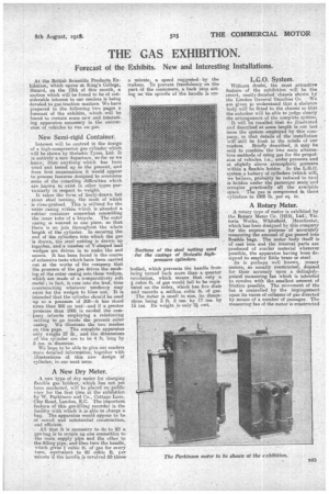
Jolly Automatic Cut-off Valve.
Mr:V. C. Jolly, engineer-in-charge to the United Automobile Services, Ltd., of Bishop Auckland, will.be showing his automatic cut-off gas-filling valve which eliminates the possibility of overcharging a flexible bag, with its consequent deterrent effects 'upon the casing of the bag.
The Jolly cut-off valve is automatic in action, being brought into play when the bag has received its full charge. A con
nection js provided between the gas bag and gas valve in the inlet or charging pipe, so that when the bag is sufficiently inflated the valve is caused to close. The gas valve is provided with a butterfly valve, the spindle of which carries, outside the filling pipe, an arm or lever to which a spring is connected, thereby tending to close the valve. The latter is held in an open position during charging by means of a trigger or trip lever pivoted on a pin fixed in a. bracket which is fitted to a suitable part of the vehicle, engaging with a notched or shouldered part at the end of one side of the valve arm. The trigger is normally maintained in engagement with the valve arm by means of a spring surrounding the pin or pivot about which. the trigger turns, the upper part. of the gas bag being confleeted by some flexible means to the trigger. The result of this arrangement is that when the gas beg rises, and is sufficiently inflated, the connection between the bag and the trigger is operated and the trigger lifted out of engagement with the valve arm, which . is immediately closed be its spring and thus automatically cutting off the supply of gas.
The diagram which we include herewith .shows the device fitted . in a vertical position and also .shows connections made to the container as fitted to vehicles run by the United Automobile
Services, Ltd. The automatic "valve, however, can quite easily be fitted in a horizontal or any other position desired.
Flugel Exhibits.
Amongst the exhibits to be staged by Flugel and Co., Ltd., 33a, Green Lanes, Newington Green, N., will be one of the company's gas carburetters, a reducing valve, and a section of a high-pressure steel cylinder for compressed gas as submitted by Mr. Flugel at a meeting of the Gas Traction Committee when he was called as a witness.
From the illustration of the carburetter which we reproduce herewith it will be seen that the gas intake is at A, the gas passing through the channel (B) of the casting (C) and out of the screw-down gas valve at D into the interior of the main casing (E), where it mixes with the air which is drawn in at F, passing out towards the right into the engine manifold. The two valves (F and D) can be opened
and closed simultaneou.sly, their adjustment and relationship being provided for by the slackening of the lock boltr (K), and the sliding of the barrel of the air valve (F) to the right or left of the spindle on which it is mounted. By means of the lever (G) the position of the two valves (F and D) can be adjusted to the requirements of the engine, the valve spindle extension travelling along the (pick pitch thread, the end of which is shown at H. For very slow running, a pinhole is formed in the end of the nozzle (L), and gas is fed to it through. the channel (M) by the hole IN) drilled at an angle to the seat of the valve (D), so that when the valve is closed there is just sufficient gas passing through the nozzle (L) to enable the engine to run light.
The dashboard equipment of the Flugel system of high compression is both neat and simple. We have had occasion to describe the Flugel reducing valve in previous issues. Three feeds, one from each unit of cylinders, are brought to a high pressure gauge, the reading upon the dial of which serves to inform the driver of the pressure remaining in the cylinders. Should any one of the bottles develop a defect it is a simple matter to disconnect the pipe connection to the defective bottle and seal the end to prevent any escape of gas. From the high pressure gauge and Ave-way piece the gas passes to the reducing valve, where the pressure of the gag is lowered.
The design and construction of the cylinder used in the Flugel system of compression is now well known.
Motor Gas Equipment Associa tion.
The Motor Gas Equipment Association, of 7, Sackville Street, London, W., is exhibiting fabric in process of manufacture, also finished material, made to the specification of the Gas Traction Committee, together with a model . flexible container and tray.
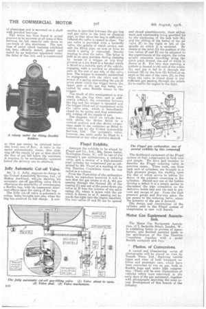
Photos. of Conversions.
A varied and illuminating series of photographs will be placed CM view by Temple -Press, Ltd., depicting various types and sizes of both transport vehicles and passenger cars, which have been converted to run on gas, both in flexible bags andunder high compression. !There will be seen illustrations of vehicles which were converted in the early days of the gas movement, together with photographs depicting the most recent development of this branch of the industry_