


Improved Hydraulic Master Cylinder
Page 82
If you've noticed an error in this article please click here to report it so we can fix it.
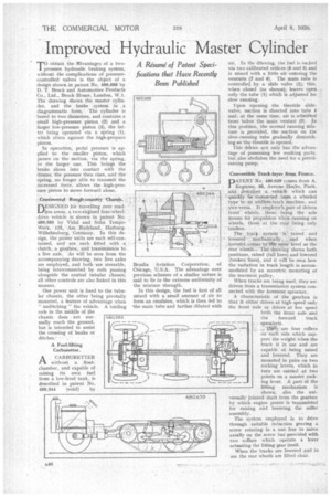
MO• obtain the rilvantages of a two pressure hydraulic braking system, without the complications of pressurecontrolled valves is the object of a design shown in patent No. 480,688 by D. T. Brock and Automotive Products Co., Ltd., Brock House, London, W.1. The drawing Shows the master cylinder, and the brake system in .• a diagrammatic form. The cylinder is bored to two diameters, and contains a small high-pressure piston (2) and a larger low-pressure piston (3), the latter being operated via a spring (1), which abuts against the high-pressure piston.
In operation, pedal pressure is applied to the smaller piston, which passes on the motion, via the spring, to the larger one. This brings the brake shoes into contact with the drums, the pressure then rises, and the spring, no longer .able to transmit the increased force, allows the high-pressure piston to move forward alone.
_Continental • -ROSIghecountry -Claussis.
riESIGNED far travelling over road
less areas, a two-engined four-wheeldrive vehicle is shown in patent No. 480,585 by Vidal and Sohn TempoWerk, 125,. Am .Radeland,. HarburgN-Vilhelmsburg, Germany. In this design, the poWer units are each self-contained, and are each fitted with a. clutch, .a gearbox, and transmission to a live axle. As will be seen from the accompanying drawing, two live axles are employed, and both are steerable, being interconnected by rods passing alongside the central tubular chassis; all other controls arc also linked in this manner.
One power unit is fixed to the tubular chassis, the other being pivotally mounted, a feature of advantage when " unditching " the vehicle. A trailing axle in the middle of the chassis does not normally reach the ground. but is intended to assist the crossing of banks or ditches.• • . • A Fuel-lifting Carburetter.
kCARBURETTER without a floatchamber, and capable of raising its own fuel from a low-level tank, is described in patent No.
480,344 (void) by air. In the drawing, the fuel is sucked via two calibrated orifices .(8 and 5) and is mixed with a little air entering the venturis (7 and 6). The main tube is controlled by a slide valve (2); this, when closed (as shown):, leaves open only the tube (1) which is adjusted for slow running.
Upon opening the throttle slidevalve, suction is directed into tube 4 and, at the same time, air is admitted from below the main venturi (3). In this position, the normal running Mixture is provided, the suction on the slow-running tube gradually diminishing as the throttle is opened. • This delrice not only has the advantage of possessing few working parts, bitealso abolishes the need for a petrolraisi rig pump.
Convertible Track-layer from France.
D4TENT No. 480,6B6 tomes from A. Kegresse, 34, Avenue Hocht, Paris, and describes a vehicle which can • quickly be converted-from a wheeled type. to an endless-track .machine, and _:vice-versa, It employs 'a pair of driven front Wheels, these being the sole means for propulsion when running on Wheels, those at the rear being only
trailers.
The ts-a4 system • is-. raised and lowered mechanically„ ..„:.and when lowered comes to."tlie-sarae`level as the tear wheels..: Thd,•draiving shows both positions, raised (full lines) and lowered (broken lines), and it will be seen how the vatiation in track length is accommodated by an eccentric mounting of the rearmost pulley,
When tracks are being used, they are driven from a transmission system connected with the foremost sprocket.
A characteristic of the gearbox is that it either drives at high speed only the front axle or drives at low speed both the front axle and tittrward track
s xko
are four rollers on each side which support the weight when the track is in use and are capable of being raised and lowered. They are mounted in pairs on two rocking levers, which in turn are carried at two points on a master rocking lever. A part of the lifting mechanism is shown, also the universally jointed shaft from the gearbox by which engine power is transmitted for raising and lowering the roller assembly.
The system employed is to drive through suitable reduction gearing a screw rotating in a nut free to move axially on the screw but provided with two collars Which operate a lever actuating the lifting gear itself, When the tracks are lowered and in use the rear wheels are lifted clear,