


A British Servo Steering Gear
Page 73
If you've noticed an error in this article please click here to report it so we can fix it.
WHILST makers of the biggest VV vehicles employed in this country, in conjunction with steering-gear specialists, have tackled, with marked success, the problem of achieving easy steering, further improvements in this field, to keep pace with progress in other directions, may prove impossible without recourse to power assistance.
An indication of a tendency towards
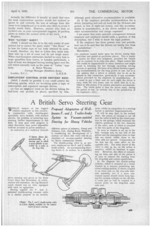
A layout, shown diagrammatically, of a steering gear in which a servo-cylinder is controlled ly a valve in the drag link.
servo steering was given at the Earls Court Show last November, at which, readers will remember, the big Henschel coach chassis was on view, equipped with such an apparatus.
Having applied the F. and J. patented double-acting vacuum valve to a similar purpose in an entirely
form, whilst an adaptation to a steering layout is sketched diagrammatically.
It will be seen that, in the normal state, the source of vacuum is cut off and the valve is held in the closed position by the springs, which maintain the relative positions of the two elements of the valve, each of which is attached to the two parts of the drag-link.
So soon as tension is set up in the link, vacuum acts on one side of the piston and the atmosphere holes to that side are closed, whilst those to the other side are opened. Compression of the link has the same effect on the opposite side. The total travel of the valve is only 110in., so the action is sensitive, whilst no backlash is apparent. Moreover, the effect of exhausting air from one side of the piston is at once to remove the loading from the drag-link and restore equilibrium.
In the diagram the double-acting cylinder, which is mounted on a frame bracket in a manner permitting universal rocking motion, is shown coupled to an extra arm on the near-side stubaxle assembly, but if a more convenient layout should result from having the vacuum cylinder on the off side, it could just as well be coupled to a second point on the drag-link stubaxle arm.