


SOME VALVE-SEATING TOOLS.
Page 29
If you've noticed an error in this article please click here to report it so we can fix it.
Interesting Devices Made by Our Driver and Mechanic Readers.
WE HAVE a number of interesting letters before us this week, describing tools for facilitating the manipulation of engine valves. There are tools for removing -the valves, for truing-up their faces when they are removed, one for facilitating withdrawal of Maudslay valve cages, and another for enabling those cages efficiently to be ground in on
their seatings. .
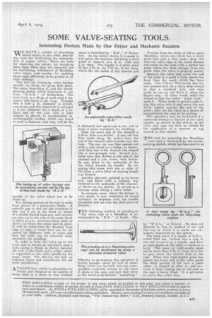
The tool for truing-up valve facings should, we think, be given first place. The letter describing it, and the accompanying sketch which illustrates it, are from " H.A.B.," of Rotherham. The main body is a block of mild steel 3 ins. square and about 3 ins. long. Through this a hole in, diameter is drilled, and at one end this same hole is enlarged to 2 ins, diameter for a depth of in. Each end of the On. hole is then tapped, as shown, to accommodate interchangeable bushes, which are bored to such a diameter that they will fit the spindle of the valve -which has te be trued up.
The cutting portion of the tool is made from pieces of a power-saw blade. A suitable gap or slot for the reception of this tool is cut in the block by means of a double-bladed haek-saw, and recesses are also cut in the side of the same blockto allow of 4i-in. setscrews being used, as shown, to retain the cutter bars in place. It will be noted that the distance from edge to edge of these bars can be adjusted for different sizes of valve and that the tools can he removed when necessary for grinding.
In order to hold the valve up to the tools and to ensure an automatic feed a light spring is fitted, as shown, between: the face of the block arid a collar, which is supported on the valve spindle by the -Usual cotter. For driving the tool an ordinary braceand screwdriver bit are quite satisfactory.
-A VALVE lifter which is.adjustable for length and designed to be capable of being used in a more or less confined
space is described by " E.B.," of Hounslow. As the sketch shows, it is made in two parts, the business end being a short
piece of channel iron in. wide and in. deep: The handle is. a plain piece of bar 5-16 in. by 7-16 in., 8 ins: long; which fits the inside of the channel and
is flattened and upturned at one end to make it more convenient for handling.
Near the outer end of the ehannel a 5-16-in, hole was drilled. A saw cut was then made along the centre from the end of the Channel untilit broke into this hole. The saw cut was then opened out with a cold chisel or a wedge, as shown, until that end of the channel was shaped like a two-pronged fork. Several 4-111. holes were then drilled in the web of the channel and a 4-in. screw, with butterfly nut, fitted to the underside of the bar which formed the handle. By engaging this screw with one or other of the holes a valve lifter of varying length was formed.
Another setscrew, pointed at its lower end, and fitted with a locknut, was fastened to the underside of the channel, as shown on the sketch. It served as a fulcrum when lifting a valve collar.
In extreme cases, where the bonnet is very small, it may sometimes be found necessary to dispense with the handle altogether and use only the short piece of channel.
THE following method of grinding-in the valve cage of a Maud:slay is recommended by " R.R.," of Leeds. The difficulty in performing this operation is mainly brought about by lack of something which can be held, but our correspondent evidently fastens an old valve in place in the cage and uses that valve as the much-to-be-desired "something."
Procure from the stock of old or spare Maudslay valves one which has a fairly good face and a true stem; drop this into the valve cage in the usual manner and mark on the stem with a scriber the point where the stem emerges from the guide when the valve is properly seated.
Remove the valve and screw the end of the stem to a poiht a little nearer the head than the mark which has been made. Use 7-16-in.. Whitworth dies for this purpose and cut a fairly deep thread so that a standard Zrin. nut may easily be ran up and down it, using the fingers only. In other words, make the thread so that the nut is " finger tight " upon it-. When ready to grind a cage in, slip this valve into it and screw the nut fairly tightly against the, end of the guide; then use the valve as a means of "manipulating the cage in its seating.
This operation may be facilitated if a square be formed on the end of the valve spindle, as shown in the sketch, as the valve and cage can then be turned by the application of a spanner or tap wrench to this square.
by "W.A.L.," of Bristol. He does not describe it, but its method of use and the way in which it is made are ade. quately illustrated by the sketch.
The main piece is a length of 5-16-in. round tteel bar, formed into a ring at one end to serve as a handle, and bent at right-angles at the other to serve as a hook. The piece at right-angles must not be more than 7-16 in. long, as it has to pass down the central hole in the cage. When this right-angled piece has passed the lower end of the valve guide the other portion of the tool, a plain cotter, is slipped in after it, and prevents it from coming out of the hole as the cage is being lifted. It is advisable to curve the cotter face.