 1
1 2
2 3
3 4
4 5
5 6
6 7
7 8
8 9
9 10
10 11
11 12
12 13
13 14
14 15
15 16
16 17
17 18
18 19
19 20
20 21
21 22
22 23
23 24
24 25
25 26
26 27
27 28
28 29
29 30
30 31
31 32
32 33
33 34
34 35
35 36
36 37
37 38
38 39
39 40
40 41
41 42
42 43
43 44
44 45
45 46
46 47
47 48
48 49
49 50
50 51
51 52
52 53
53 54
54 55
55 56
56 57
57 58
58 59
59 60
60 61
61 62
62 63
63 64
64 65
65 66
66 67
67 68
68 69
69 70
70 71
71 72
72 73
73 74
74 75
75 76
76 77
77 78
78 79
79 80
80 81
81 82
82 83
83 84
84 85
85 86
86 87
87 88
88 89
89 90
90 91
91 92
92 93
93 94
94 95
95 96
96 97
97 98
98 99
99 100
100 101
101 102
102 103
103 104
104 105
105 106
106 107
107 108
108 109
109 110
110 111
111 112
112 113
113 114
114 115
115 116
116 117
117 118
118 119
119 120
120 121
121 122
122 123
123 124
124 125
125 126
126 127
127 128
128 129
129 130
130 131
131 132
132 133
133 134
134 135
135 136
136 HORIZONTAL ENGINE
Page 73
Page 74
If you've noticed an error in this article please click here to report it so we can fix it.
at rear of new Stepless-floor Daimler
THE prototype of an intriguing development of the Daimler Fleetline rear-engined double-decker chassis will be exhibited on the stand of Transport Vehicles (Daimler), Ltd., in a fortnight's time. Designated the SRD 6 single-decker chassis, this latest Daimler model is a 36-ft. design with the horizontal power unit mounted transversely across the rear of the chassis frame. The layout is such that the main floor height over the engine compartment is 15.625 in. above the chassis-frame height between the wheels, this being 21.25 in. above ground level in the unladen condition. The unladen entrance step height promises to be 1.5.5 in., and thechassis layout permits a gently ramped floor rearwards from the entrance step to, the rearmost row of seats.
It must be emphasized that the Show exhibit is only a prototype and that production versions will be lighter with a much . neater chassis rear-end assembly. Indeed, the example to be displayed has the same side-member profile at the rear . end as the Fleetline, the fabricated framing assembly which supports the engine and transmission being bolted to the side-members, whereas production chassis will have side-members which incorporate much of the rear structure as an integral part.
So like the Fleetline is the new design, in fact, that virtually the .whole of the chassis ahead of the rear-axle centre line . is identical except that the centre sidemember sections have been lengthened by 2 ft. 3 in. to give a wheelbase of 18 It. 6 in. This has entailed repositioning a cross-member and its adjacent outriggers.
The radiator is mounted at the extreme front of the new chassis, whereas on the Fleetline it is . at the right-hand rear corner. Air is drawn through the radiator by an electrically driven thermostatically controlled eightbladed fan; the slight intrusion into the loading-platform space occasioned by the radiator cowling is not of great significance in a single-decker.
The rear-end_ assembly consists basically of 10-in, by 3-in. by 0.1875-in, pressed-steel channels bolted together. The rearmost transverse member is 94 in. wide, and from each end of it longitudinal channels extend -forward to just behind the rear wheels, the front ends of the side channels being gusseted to transverse channels at each side, which. in turn are gusseted to deep plates which are bolted to the swept-down ends of the main side-members. These plates have an inverted-L section, and flanges lying in the same plane as the tops of the main side-members, where they are swept up over the rear axle, and the plates themselves extend rearwards as far as the ends of the main side-members.
On the inner side of the main sidemembers there are further inverted-Lsection plates, also bolted, and the rear ends of each pair of plates support a full-width cross-member which is 10 in. 'deep at its outer ends but is only 5 in. deep in the centre, this reduced-depth section being some 44 in, wide, i.e., the
same width as the main chassis frame.
Between this dropped-centre member and the rearmost member there is a longitudinal member, this being located 4.25 in. to the right of the chassis centre line. This longitudinal is a 6-in. by 5-in. channel, face.. downwards, and at its forward end it curves downwards to meet the upper flange of the dropped-centre cross-member, thus facilitating the provision of a shallow ramp up to the rear platform from a gently sloping central gangway, there being no actual steps anywhere along the gangway.
From the cranked longitudinal a 10-in.deep channel extends to the right-hand outer channel, and this has one tubular and one channel-section member bolted between it and the outer end of the dropped-centre member to provide mounting points for the gearbox. The space to the left of the cranked longitudinal contains no framing members, being occupied by the power unit.
The engine of the Show exhibit will be a Daimler Mark VIII 8.6-litre six-cylinder diesel engine, developing 125 b.h.p. at 2,000 r.p.m. and 345 lb.-ft. torque at 1,200 r.p.m. Alternative to this a turbocharged version developing 150 b.h.p. and 455 lb.-ft. torque will be offered, with the further options of Gardner 6HLW 112b.h.p. and 6GLX 150-b.h.p. engines.
Because it is desirable to keep the engine accessories on the upper side of
the cylinder block, with the heads facing towards the, rear, it has been necessary to, in effect, " reverse-" the cylinder block so that power is taken from what would appear to be the front of the engine. Compared with the standard Daimler unit, the direction of rotation of the crankshaft has had to be reversed by employing a special camshaft so that the input at the ged-box has the correct rotational direction..
Although the tdrm "horizontal " has been used when ileferring to the engine location, it actually lies at an angle of 10' to the horizontal, with the crankshaft centre-line on the sane plane,as the midaxle section of the main side-members, and 60 in. behind the rear-axle centreline. The engine, which carries an 18-in.diameter open-circuit hydraulic coupling. has a four-point mounting, with two• Metalastik rubber sandwiches in compression and shear at each end of the unit.
At the left-hand end of the engine the two mountings have an inverted-V disposition, the mounting feet on the engine being cast integral with the timing-gear cover. At the other end of the engine there is a large 0.375-in.-thick plate which permits wide spacing of the two rubber mountings at that end. Transverse movement of the engine is restricted by a rubber bushed arm, with a torsional damper connected to the bottom of the crankcase.
The output side of the hydraulic coupling carries a trailing-link coupling joining it to the combined Daimatic semiautomatic gearbox and bevel-gear assembly, this being identical to that used in the Daimler-engined Fleetline. The gearbox-bevelbox assembly is slung from the two short longitudinal members already referred to, using four rubber bushes. From the output flange of the bevelbox a short propeller shaft takes the drive to the Fleetline-type droppedcentre rear axle.
Production versions of the SRD 6 are likely to have a different engine and transmission layout, with the power unit on the right-hand side of the frame, a slightly modified gearbox-bevelbox assembly to the left of it and a conventional centredifferential driving axle, the droppedcentre type being unnecessarily heavy and complicated when, as in the case of this model, there will be ample space above the axle. This proposed layout will have the advantage that perfectly standard horizontal-type engines can be used, no crankshaft-rotation reversing being necessary.
In all other respects the rest of the chassis is basically Daimler Fleetline. Similar springs are used, these being 4 in. by 50 in. (dual-rate) at the front and 4 in. by 62 in. at the rear, with lever-type dampers at the front and telescop:c dampers at the rear. The braking system is Bendix-Westinghouse air-pressure, with Daimler strut-type '16-in. brakes incorporating automatic adjusters and having a total lining area of 733 sq. in. Daimler worm-and-nut steering is used and l0.0120 (14-ply) or braced-tread tyres are fitted at both axles.
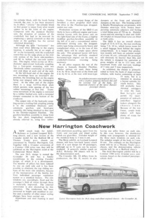
The SRD 6 has an overall chassis length of 33 ft. 0,75 in., the rear overhang being 7 ft. 10 in., which leaves room for a small luggage boot behind the engine compartment. It is hoped that production models will have an unladen weight of 4 tons 18 cwt., although the prototype will obviously be heavier than this, and the vehicle is designed for operation at gross weights of up to 13.5 tons, with maximum frontand rear-axle loadings of 5 tons and 9 tons respectively.
As exhibited, the chassis is primarily suited to form the basis of stage-carriage vehicles, with bodies containing at least 53 seats, but it is intended to develop a layout suitable for coach bodies. This will probably have elevated outriggers to raise the body floor height and permit the incorporation of mid-axle underfloor luggale lockers alongside the chassis frame. Because of the low frame, coach body makers will have plenty of scope for new ideas.