


A Flexibly Mounted Flywheel
Page 36
If you've noticed an error in this article please click here to report it so we can fix it.
THE large mass of an engine flywheel is v.ay resistant to erratic movement, and if mounted slightly out of truth will impose undue stresses on the crankshaft in its efforts to revolve concentrically. To permit this action to occur, and to provide a 'measure of torsional resilience, is th, objebt of a resilient mounting shown in patent No. 569,963, by G. Stanley, Gwynant House, Beddgelert, Caernarvon.
In the drawing, the crankshaft is shown fitted with a flange (1) to which the flywheel would normally be bolted. In this case, however, a flanged extension (2), rigid with the crankshaft, receives the flywheel, which is loosely spigoted and restrained axially by bolts fitted with, spacer collars (3), which permit a working clearance.
The torque is transmitted via a set of springy spider arms (4) attached, on their inner ends, to the crankshaft, and at their other ends to the flywheel, with the interposition of spring washers (5). By this means, the flywheel can revolve truly should the crankshaft be slightly out of alignment.
AN AMERICAN DESIGN FOR A TIPPING BODY
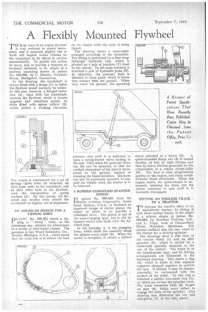
PAIENT No. 569,881 shows a tipping or " dump " body, as the Americans say, suitable for attachment to a trailer or semi-trailer chassis. The patentee is Gar Wood Industries, Inc., Detroit, Michigan, U.S.A., which states that the main aim is to relieve the load
on the chassis while the body is being tipped.
The drawing shows a semi-trailer arranged according to the invention. The lifting is performed by a four-stage telescopic hydraulic ram, which is pivoted on a pair of brackets (1) fixed • to the chassis. To the same brackets is attached a pair of hydraulic jacks (2). In operation, the pressure fluid is directed to these jacks, which it forces into contact with the ground. When they reach the ground, the operating pressure rises until it is sufficient to open a spring-loaded valve leading to the ram. Only when the jacks are down can the ram be operated, so that the vertical component of the load is transferred to the ground, instead of stressing the frame members. The jacks can also be separately operated to support the vehicle when the tractor is to be removed.
A RUBBER-CUSHIONED STARTERPINION IN patent No. 569,649, from the Bendix Aviation -Corporation, South Bend, Indiana, U.S.A., is disclosed an improved design of starter pinion the object of which is to provide a cushioned drive. The pinion is not of the auto-engaging type, but is slid by manual means into mesh with the flywheel ring.
In the drawing, 1, is the engaging lever, which slides the assembly along the splined motor shaft (2). When the motor is energized, it rotates a splined sleeve attached to a barrel (3). A quick-threaded flange nut (4) is turned thereby, at first by light friction and then by heavy friction generated by the compression of a rubber thrust-collar (5). The load is thus progressively applied to the engine, and sharp metalto-metal shock eliminated. When the engine starts, the quick-thread is unscrewed, releasing the drive, but the pinion continues to spin until it is manually disengaged.
• FITTING AN ENDLESS TRACK TO -A TRACTOR TO Increase the tractive effort of an agricultural tractor, by fitting it with, short endless tracks, is the object -of a scheme shown in patent No. 569,885, by Roadless Traction, Ltd., and L. Tripp, both of Gunnersbury House, Hounslow, Middlesex. The scheme outlined uses the rear wheel of the tractor for a driving sprocket.
The drawings show a side view of the tractor. wheel (I) and an idler sprocket (2), which is carried by a framework specially attached to the rear of the trabtor. •The track is of the locked-girder type, and its driving arrangements are illustrated in the sectioned drawing. This shows a ring (3), which is made in four separate segments clamped together to encircle the tyre. If desired, it may be shaped, internally, to correspond with the pattern of the tread. To this ring is attached a similar four-piece ring (4), on which are formed the sprocket teeth. The track comprises links (5) hinged on pins (6), which carry rollers to engage the teeth of the sprocket. This drawing also illustrates the rim and side-plates (7) of the, idler wheel.