


Patents Completed.
Page 20
If you've noticed an error in this article please click here to report it so we can fix it.
Rotary-valve EngineCushion Tire Construction. Cleaning Oil Cases.
Renault Centrifugal Magneto Governor.
Copies of complete specifications of the patents published on this page can be obtained from the Sales Branch, Patent Office, Holborn, W.C., at the cost of sixpence for each specification.
H. 0. WILKINSON) No. 100,761, dated 23rd February, 1916.—The valve forming the subject of this ifivention is mounted above the cylinders in an internal-combustion engine. It comprises a fixed inner tube or manifold and two concentric rotating sleeves outside it. The manifold is provided with internal partitions dividing it up into inlet and exhaust passages and water spaces.
The two outer sleeves rotate in opposite directions so as to give rapid opening and closing of the ports communicating with the engine cylinders. Adjustment, of the sleeves and compensation for wear is effected by splitting the fixed inner tube at one side for the greater portion of its length, and springing this part outwards by means of set screws to fit tightly against the inner sleeve.
The inner rotating sleeve is made longer than the outer one, and each carries a helical pinion at its end. The drive is transmitted directly from the crankshaft to the inner sleeve and through a countershaft to the outer sleeve.
JOHN SLEE, No. 10,754, dated 21st July, 1915.—A cushion tire of which the drawings show a side view of a segment partly in section and a cross-section. The tire may be considered as two rings, one within the other, united by a series of cross-bolts. The inner ring consists of the standard, wheel rim, used without alteration, to which is attached a. series of cushion pieces held firmly to the rim by a band bolt. The tread of the tire may be made up of segments, as shown in the first figure, joined together or made as a continuous ring. To the inside of the tread, pieces shaped similarly to the cushion pieces are fastened, both pieces having eye-holes to admit the cross-bolts. The tread run is made up of two rings with flanges to hold the tread. The cross-bolts hold these flanges against each other, enclosing the tread and a centre piece recessed on both sides. J. B. FEeausex, No. 14,820, dated 20th October, 1915.— This invention relates to gear-cases, axle-cases and the like which are used as oil-baths. The accompanying drawings show the application of the invention to a live-axle casing. A sediment chamber is formed on one of the side walls, above the bottom of the casing, so that it does not interfere with the ground clearance. A drip-shoulder is provided on the inside of the casing above this chamber, so that the sediment, chips, etc., thrown up by the gearing with the oil strikes the wall of the casing and falls back into the special chamber ; the oil overflows from the chamber, but the sediment is retained in it. A plug-cock at the bottom of the chamber permits the refuse with only a small quantity of oil in the chamber to be removed. This plug-cock is preferably a two-way cock, and it may be used for emptying the sediment chamber and some other purpose, such as testing the level of the oil.
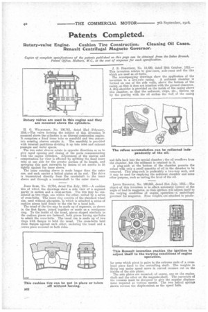
Lours RENAULT, No. 100,868, dated 21st July, 1915.—The object of this invention is to effect automatic control of the angle of lead in magnetos, so that ignition will adjust itself to the varying conditions of engine operation—a centrifugal governor for magnetos. Four weights are attached to pendu lar arms which pivot in pairs to the extreme ends of a crosshead piece fixed to the controlling shaft. The weights in flying out under speed move in curved recesses cut, on the insides of the side plater.
The side plates are mounted, of course, one on the engine.. shaft and the other on the magneto-shaft. The curvature of the recesses must be designed to give the angular displacement required at various speeds. The two helical springs shown reverse the displacement as the speed falls.