


Constant-clearance Device for Brakes
Page 34
If you've noticed an error in this article please click here to report it so we can fix it.
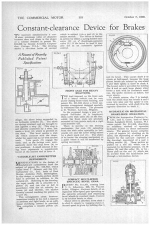
maintain automatically a con stant minimum value of clearance between shoe and drum is the object of a scheme detailed in patent No. 511,035 by Bendix Aviation Corporation, Chicago, U.S.A. The drawing shows a two-shoe brake of normal design, the shoes being expanded by an hydraulic cylinder (1). The shoes are spring returned, and are brought to rest against a stop (2). This stop is not directly contacted by a shoe, but meets a lever (4) which is pivoted on
one shoe. This lever carries a stub (3) which contacts with the drum, whilst the upper end is cut with ratchet teeth. Twin pawls (5) engage the teeth, and, as the facings wear, automatically move the stop lever (4) to new positions. A small amount of facing wear represents a considerable travel of the ratchet end of lever 4.
VARIABLE-JET CARBURETTER REFINEMENT.
NiTODIFICATIONS in the design of /111variable-jet carburetters form the subject of patent No. 510,753. which comes from T. Skinner and the S.U. Carburetter Co., Ltd., both of East Works, Adderley Park, Birmingham. In this design, a variable-section choke tube is provided in addition to the variable jet. Referring to the drawing, the taper needle (6) is attached to a piston (7) and can rise or fall in accordance with the air velocity between jet and throttle, the suction thereby created reaching the piston via a port (5).
This arrangement alone, however. sometimes results in too rich a mixture at medium and light loads, so an additional rectifying control is provided. This comprises a smaller piston (3).
a32
which is subject (via a port 4) to the intake suction. The device is limited in action by either a spring-loaded ball-. valve (2) or adiaphragm-operated valve (1); if the latter be used it may also act as an automatic ignition control.
FRONT AXLE FOR HEAVY REACTIONS.
THE load imposed on the front axle of a heavy vehicle can be very severe during front-wheel braking, and patent No. 511,343 shows a front suspension arrangement designed specially to withstand this stress. The patentee is M. Wottier, Antwerp, Belgium.
In the proposed design a pair of Vshaped half-axles (3) is employed; these carry stub axles (6) at the rear, whilst the front ends are pivotally mounted at two points each on a rigid cross-member (2).
There is novelty in the steering mechanism, the rods (5) extending from the stub axles upwardly to bellcranks (4) and the latter being united by a short track rod (1). The object is to locate the steering mechanism at a point where it will be unaffected by spring movement.
COMPACT MULTI-SPEED EPICYCLIC BEVEL GEAR.
pATENT No. 511,371, coming from J. G. Johnstone, 200, St. Vincent Street, Glasgow, discloses details of an ingenious three-speed gear operating on the epicyclic principle and employing bevel wheels in constant mesh. Control is by friction bands or discs.
Direct drive is afforded, from shaft 1 to shaft 3, simply by engaging clutch 2. Second speed is given by holding disc 5
and its bevel. This causes shaft 3 to rotate at half-speed, because the large planet bevels are rotated by sun-wheel 4 and their spider is fixed to shaft 3. The lowest ratio is provided by holding disc 8 and as each large planet wheel forms a unit with its concentric small one, the spider revolves as before, hul more slowly.
To obtain reverse, disc 7 is braked, with the result that sun bevels 4 and f come into play and the spider is constrained to revolve, with shaft 3 in flu opposite direction to shaft 1.
HYDRAULIC OR MECHANICAL BRAKE-SHOE OPERATION.
FROM the Automotive Products Co. Ltd., and G. Gates, both of Brod House, Langham Street, London, W.1
comes patent No. 511,300, describint an auxiliary method of operatint hydraulic brakes by direct mechanica means. The general layout comprise: a pair of tappets (4) abutting on thf shoes, the separating of which is per formed by the outward (upward it the drawing) movement of a pair o rolling sectors (5). These sectors an pulled by a rod (6) which can b. operated by hydraulic pressuie, via th piston (3) and the collar (2), or by direct pull on the rod (1) which ma: be worked from the hand-brake leve through a lost-motion device.