


Differential Locks in Four-wheel-drive Layout
Page 34
If you've noticed an error in this article please click here to report it so we can fix it.
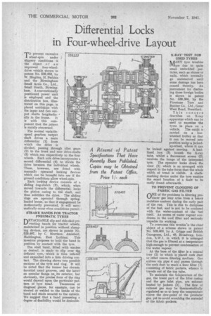
A Resume of Patent Specifications That Have Recently Been Published. Copies may be Obtained from the Patent Office, Price 11each
TIprevent excessive wheel-spin under slippery conditions is
the object .o a n' improved four-wheeldrive vehicle shown in patent No. 539,253, by W. Blagden, H. Perkins and the Birmingham Small Arms Co., Ltd., Small Heath, Birmingham. A conventionally positioned power unit is employed and the distribution box, illustrated on this page, is placed amidships with the input and two output shafts longitudinally in the frame. It is with this component that the patent is mainly cencerned.
The normal variablespeed gearbox output shaft drives a main differential (1) from which the drive is divided, passing through idler gears (2) to the front and rear drive-shafts (3) which ran respectively to the lour wheels. Each axle drive incorporates a second differential (4) to divide the drive between the individual wheels. These, however, are fitted with manually operated locking devices which can be brought into use • if the ground conditions allow wheel-spin.
Each locking device consists of a sliding dog-clutch (5) , which, when moved towards the differential, locks
• the pinion casing to th6 shaft, and thus solidifies the drive. The sliding dogs are operated through springloaded levers, so that if engagement be moenentarily prevented, it will automatically occur when conditions permit.,
STRAKE BANDS FOR TRACTOR PNEUMATIC TYRES
DETACHABLE slip and side-skid preventing bands for tractor wheels, maintained in position without clamping devices, are .shown in patent No. .539,407, by C. Morrison, Amisfield, Haddington, East Lothian. This inventor proposes to hold the band in position by contact with the tyrc.
The steel band, fitted with strakes ars desired, is made to slip over tte deflated tyre, which is then inflated and expanded into a firm driving context. The drawing shows two possible sections of the tyre and ring. It will be noted that the former has circumferential tread grooves, and the latter an annular flange on its exterior, but obviously, the precise'. form of the ring would, depend upon the particular pat
tern of tyre tread. Transverse or diagonal pieces, for example, can be riveted or welded to the inside of the band and studs secured to the outside. We suggest that a band possessing a degree of flexibility would be desirable. X-RAY' TEST FOR USED TYRES NAANY tyre troubles f-Viare due to quite small embedded par ticles, such as stones or nails, which normally go undetected until some damage has been caused thereby. An :instrument for disclosing these foreign bodies • is shown in patent No. 539,304, by the Firestone Tyre and Rubber Co., Ltd., Great West Road, Brentford.
This concern describes an X-ray apparatus which can be used to examine the tyres in place on a vehicle. The outfit is carried on a lowwheeled trolley so that it can be moved into position under a jackednp-wheel, where it can be locked against moving. A leadlined box (3) houses' the X-ray tube, whilst a fluorescent screen f2) receives the image of the interposed tyre. The operator looks down the visor (1) which is so arranged with respect to the tube focus that the whole width of tread is visible. A chalkmarking device under the tyre enables the exact location of a fault to be easily found afterwards.
TO PREVENT CLOGGING OF FABRIC GAS FILTER
ONE of the problems in filtering producer gas may arise from a heavy moisture content during the early part of the run. This is due to dampness of the fuel, and is not to be confused with the water-content of the fuel itself. An excess of water vapour condenses in the cool filter and seriously impedes its working. • To overcome this trouble.is the chief object of a scheme shown in patent No. 539,403, by A. Griggs and British Gazogenes, Ltd., 48, Broadway, London, S.W.1, in which it is arranged that the gas is filtered at a temperature high enough to prevent condensation ef the water vapour.
At the base of the filter is a conical tray (2) in which is placed cork dust or other coarse filtering medium. Gas arriVes via pipe 4 and passes through the cork•dust to reach' a finer filter (1) consisting of fabric pockets, whence it travels out of the top tube.
To maintain the tefiiperature of the gas, the lower part of the filter casing and the gas inlet pipe, are exhaust heated by jackets (3). The flow of exhaust gas may be thermostatically regulated so as to keep the temperature• above the dew-point of the producer' gas, yet to avoid scorching the material of the fabric pockets.