


PATENTS SUMMARIZED.
Page 22
If you've noticed an error in this article please click here to report it so we can fix it.
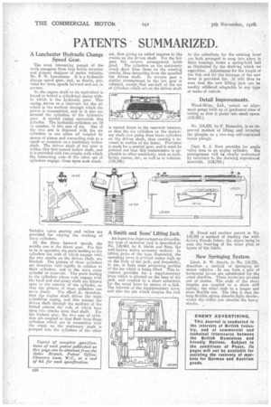
A Lanchester Hydraulic Change Speed Gear.
The most interesting patent of the week emaiiates from that, fertile inventor and pioneer designer of motor vehicles, Mr. F. W. Lanchester. It is a hydraulic change speed gear, and, as drawn, provides for three speeds forward and one in reverse. • .
To the engine shaft or its equivalent is keyed or bolted a cylindrical casing within which is the hydraulic gear. This easing serves as a reservoir for the oil which is the medium through which the power is transmitted, and to it also are secured the cylinders of the hydraulic gear. A second easing surrounds this cylinder. The hydraulic cylinders are 12 in number, in two sets of six. One of the two sets is disposed with, the six cylinders in one .plane all coupled by means of piston and connecting rods to a crank or eccentric on a stationary hollow shaft. The driven shaft of the gear is within this first named hollow shaft, and it is provided with two cranks with which -the connecting rods of the other set of cylinders engage, three upon Gash crank.
Suitable valve gearing and valves are provided for varying the working of these cylinders.
Of the three ;forward speeds, the middle one is the direct gear. For this to he in operation the ports leading to the cylinders the rods of w.Beli engage with the two cranks on the driven shaft, are blocked. The pistons of these cylinders are therefore held rigidly in relatien to their cylinders, and to the main outer cylinder or reservoir. The ports 'leading to the cylinders whose rods engage with the fixed and stationary shaft are thrown open to the interior ofthe cylinder, so that the pistons of these cylinders can
move freely. The effect is, therefore, that the engine shaft drives the mein cylindrical casing, and this rotates the driven shaft through the medium 'of the locked pistons the rods of which bear upon two cranks upon that shaft. For the highest gear, the two sets of cylinders are coupled so that fluid from those cylinders' which are in connection with the crank on the stationary shaft is pumped into the cylinders of the other
set, thus giving an added impetus to the cranks on the driven shaft. For the low gear the reverse arrangement holds :good. The cylinders on the stationary crank draw from those on the rotating cranks, thus detracting from the speed‘of the driven shaft. In reverse gear a similar arrangement to the low gear is adopted, except: that one-half. of the set of cylinders whic*.h act on the driven shaft
is vented direct to the reservoir interior, so that the six cylircders on the stationary shaft now pump from three cylinders on the driven shaft, thus causing a reversal in motion of the letter. Provision is made for a neutral gear, and it must be pointed out that this transmission is applicable to other machinery, such as tools, hosts, ranes, etc:, as well as to vehicles. (119,140.)
A Smith and Sons' Lifting Jack.
An ingenious improvement on the ordinary type of motorcar jack is deseribed_in No. 118,963, by S. Smith and Sons, the well known motor accessory makers. In lifting jacks of the type illustrated., the operating lever is pivoted rather high up on the body of the jack, and frequently, in use, it fouls some projecting portion of the car which is being lifted. This invention provides for a supplementary lever which is pivoted on the base of the jack, and coupled to a short substitute for the usual lever by means of alink. The fulcrum of the supplementary lever, and also the pin which couples the link
to the substitute for the existing lever are both arranged to snap into place in their bearings under a spriag-held ball as illustrated by the drawing which we . reproduce. Adjustment for the length of the link and for the leverage of the new lever is provided for. It Will thus be seen that the new lifting jack can be readily reridered adaptable to any type or make of vehicle.
Detail Improvements.
Wood-Milne, Ltd., patent an alignment gauge built up of graduated sizes of tubing so that it packs into small space. (118,923.) No. 114,822, by P. DessauIes, is an improved method of lifting and lowering the 'ploughs on a two-way self-contained motor plough.
Capt. S. J. Burt provides for ample valve area in an engine cylinder. His arrangement will be clearly understood by reference to the drawing reproduced herewith. (118,764.) H. Freed and another patent in No. 118,921 a method of binding the wellknown Ferodo fabric, the object being to ease the weaving of the inner plies or layers of the fabric.
New Springing System.
Lieut. A. W. Smyth, in No. 118,731, describes a method of springing: for motor vehicles. In one form a pair of horizontal levers are substituted for the usual shackles. These levers are pivoted out of . centre. The ends of the short lengths are coupled to a short stiff spring ; the other ends to a longer and more flexible one. The idea is that the long flexible spring absorbs light shocks; whilst the stiffer one absorbs the heavy shocks.