


Typical Business Motors for Heavy Loads.
Page 4
Page 5
Page 6
If you've noticed an error in this article please click here to report it so we can fix it.
The " Hallford," 5-ton, Bus or Lorry Chassis.
One of the Gold Medallists in Class E of the recent R.A.C. Trials.
_ The engineering world has not been disappointed in its expectations arising from the announcement, about a year ago, that J. and E. Hall, Limited, of Dartford, had taken up the manufacture of heavy motor vehicles. In wcuring the English patents of that excellent Swiss chassis, the Saurer, this company undoubtedly made a good stroke of business at the outset. It was not to be expected that the machine would suit the English market without some little alteration, but such departure from the original designs as were deemed desirable had been completed before the vehicles appeared in public. The resulting chassis is in every respect a fine piece of work, and, during the recent trials, through which the " Ilitilford " wagon (No. E 30) ran without a hitch, many expressions of admiration for the numerous beautiful points in its construction were heard from manufacturers and the public alike. The fact that this machine lost some 200 marks in &pelt was due to no fault of its mechanism, but merely to the unfortunate litting of tires which proved to be in bad condition.
We paid a visit to the company's works, at Dartford, when the first batch of chassis was being completed, in February last, and we enjoyed a second visit last week. Nobody who goes through the " Haliford " shops can fail to appreciate the reasons for the consistently good running of the vehicles which are manufactured and built there. The care and attention to details of manufacture; the elaborate installation of gauges, jigs, and fixtures for ensuring only the most accurate and strictly interchangeable work; the general cleanliness and intelligent appearance of the mechanics who are employed in the works; the tactful and most thorough supervision by the heads of departments; all are controlling factors in the production of this excellent lorry chassis. •
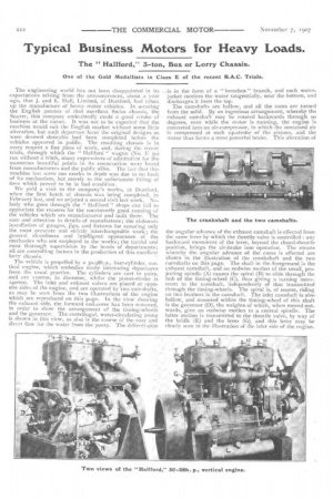
The vehicle is propelled by a 3o-38h.p., four-cylinder, vertical engine, which embodies many interesting departures from the usual practice. The cylinders are cast in pairs, and are i tomm. in diameter, whilst the piston-stroke is 40rnm. The inlet and exhaust valves are placed at opposite sides of the engine, and are operated by two camshafts, as may be seen from the two illustrations of the engine which are reproduced on this page. In the view showing the exhaust side, the forward end-cover has been removed, in order to show the arrangement of the timing-wheels and the governor. The centrifugal, water-circulating pump is shown in this view, as also is the course of the easy and direct flow for the water from the pump. The delivery-pipe is in the form of a " breeches " branch, and each waterjacket receives the water tangentially, near the bottom, and discharges it from the top.
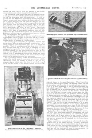
The camshafts are hollow, and all the cams are turned from the solid. By an ingenious arrangement, whereby the exhaust camshaft may be rotated backwards through 90 degrees, even while the motor is running, the engine is converted into an air-compressor, in which the contained air is compressed at each up-stroke of the pistons, and the motor thus forms a most powerful brake. This alteration of the angular advance of the exhaust camshaft is effected front the same lever by which the throttle valve is controlled : any backward movement of the lever, beyond the closed-throttle position, brings the air-brake into operation. The means whereby the angular advance of the cams is effected are shown in the illustration of the crankshaft and the two camshafts on this page. The shaft in the foreground is the exhaust camshaft, and an endwise motion of the small, pro, jecting spindle (A) causes the spiral (B) to slide through the hub of the timing-wheel (C), thus giving a turning movement to the camshaft, independently of that transmitted through the timing-wheels. The spiral is, of course, riding on two feathers in the camshaft. The inlet camshaft is also hollow, and mounted within the timing-wheel of this shaft is the governor (D), the weights of which, when moved outwards, give an endwise motion to a central spindle. The latter motion is transmitted to the throttle valve, by way of the bridle (E) and the lever (G), and this lever may be clearly seen in the illustration of the inlet side of the engine.
In the same view are also shown : ihe lever (H), by which the air-brake is operated; the hand-regulated, throttle-valve lever (j), the small dashpot (K), by the side of the can buretter, and to which we refer later; the high-tension magneto, and the method of fixing it to the crankcase ; and the reserve-oil tank (L).
Referring, now, to the exhaust side of the engine, it will be seen that the engine is lubricated by means of a small gear-pump, which is driven from the water-pump shaft through enclosed bevel-gear (M). The oil-pump draws the oil from a sump, and delivers to the branch-piece (N), in which is fitted a small relief valve, which valve lifts when the pressure of the oil reaches a predetermined amount, Inside the crankcase is a hollow rod, through which the oil is conducted from the branch (N) to the crankshaft ; the inner end of the hollow rod terminates with a strap, which en. circles the crankshaft at the point marked F on the illustra. tion showing that part. The bore of the strap has an annular groove, round which the oil can find its way to the hollow crankshaft, and thence to the big-ends of the connecting.
rods. The supply of oil can be replenished from a tank on the dashboard, or by pouring it through one of the branch pipes under the crankcase. These pipes are fitted with spring caps, one of which (0) it shown open in the exhaustside illustration of the engine.
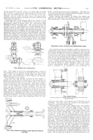
The flexibility and smooth running of this engine is greatly due to the efficient lubrication, to the mounting, on Hoffmann ball-bearings of all its shafts, and to the special form of carburetter which is employed. The latter fitting is shown, on this page, by a line drawing which gives sectional views of the double-jet chamber, together with the flap valve and the two piston valves by means of which the highest possible efficiency is obtained at all speeds of the en-. gine. When the motor is running at low speeds, the righthand-side jet is supplying the spirit, but, immediately the speed increases, the flap valve is drawn open and the other jet begins to deliver. A further increase in speed causes the flap to open more widely, thus admitting more air, and, finally, putting the first jet out of operation. The flap valve is damped by means of a small, glycerine dashpot : we have already referred to this in passing.
Before leaving the engine, to discuss the clutch and gearing, we would draw our readers' attention to the threepoint suspension, as shown in the side-views of the engine.
The clutch has been considerably modified, since the first introduction of the chassis to this country, but this has not come about through any trouble or weakness, but is simply the outcome of a desire on the part of the Dartford engineers to hring every part down to the simplest possible condition, both because of cheapening the cost of production and of making the vehicle more nearly fool-proof. As may be seen in our sectional drawing of the clutch, it is one of the ordinary, leather-faced coned type, but, instead of its having one central spring of great strength, there are three, smaller, equi-spaced, helical springs. The whole clutchgear is mounted on an extension of the crankshaft, on which part the whole of the thrust, due to driving, is selfcontained. The drive from the clutch to the gear-box is through a universally-jointed shaft.
The gear-box is of the usual, sliding type, and provides for four speeds forward, and one speed reverse. The forward speeds give 3, 6, to and 12 miles an hour. All the changes are effected by a single lever and gate-change, with stiff, square-section selector-rods. The gears are of ample size for the work, and the teeth are rather wider than is customary. • A reference to our illustration on page 235 will convey a good idea of the proportions of all the parts of this gear-box, but no illustration, however good in detail, can show the excellent material of which the gears and shafts are made. The good condition of the gears, in the chassis which took part in the recent trials, proved the quality of the material to some extent, but only by a most minute examina tion of the parts, and by their subjection to exceptional strain, can any adequate idea of their value be obtained.
We would mention that this manufacturing company is one of the few which has solved the problem of the casehardening of nickel-steel, of which material the gears are made. All the general methods of case-hardening are. un suitable for this kind of steel, on account of the brittle characteristics and nature set up in the material, The differential gear cage is one point of special interest in this gear-box : this is better shown in the sectional drawing of the bevel-gear and differential-gear. It will be noticed that the differential-gear cage is made out of two, forged, turned, and bored shafts, the inner ends of which arc of large diameter and are bored out to take the differential bevels. The latter parts have square holes through their centres, and into these the square ends of the differential shafts are slipped, thus taking the drive, from the main bevel-wheel and cage, to the Morse, silent-chain sprockets which are fixed on the outer ends of the differential shafts. This form of construction makes a very stiff job, and relieves the central shafts of all but torsional strains. Hoffmann ball-bearings are again employed here, as, indeed, they are throughout the whole chassis.
The gear-box is suspended, at the rear end, from a frame cross-member, by the two feet on the lower half of its casing, whilst the forward end of the casing rests on another crossmember which is stamped of a shape to suit.
The steering-gear is mounted in a practical manner, and has evidently been the subject of much consideration. It is of the ordinary worm-and-sector type, and is as simple as possible. There is no adjustment provided, with which to take up any slack due to wear, and, in omitting this, the designers have probably been well advised. It is an open question whether it is not better to design the parts so that they can he quickly and cheaply replaced, rather than to provide a lot of complicated adjustments, which cost much money to produce, and which, in the hands of the average driver, are a source of trouble and annoyance.
The segment (S) which is shown in our illustration of that detail, is a fourth part of a complete worm-wheel which, after being turned and hobbed, is parted off, and the rectangular spigot, which takes the place of a web, is shaped to fit into the recess in the forged spindle and lever (R) which is shown in the same illustration. When in position within the steering-gear casing, the segment cannot fall out of the socket, but, in order to prevent such an occurrence while it is being assembled, a bolt is passed through the hole which is provided. The ease with which the segment may be replaced can be well followed from the illustration of the steering-gear in position on the chassis. From that view, it will be seen that the casing extends under the sidemember of the main frame, and the latter, therefore, takes all thrust due to the operation Of the steering-gear. It will also be noticed that it is only necessary, in order to take out and replace a segment, to remove the cover (P), when the lever and spindle (R) may be withdrawn, and the segment (S) replaced, without disturbance of any other part of the chassis. The top view of the chassis enables it to be seen that, in addition to the air-brake on the engine, there are a foot-brake, which acts upon a large drum on the differential shaft, and compensated expanding brakes, which act within drums on the rear wheels. The drum for the former of these is also shown in the drawing of the differential gear.
Cables have been avoided throughout the brake system, and stout rods, with ample means of adjustment, are fitted instead. Balancing is ensured by the stiff-looking platelever, which can be seen midway on the chassis. A reference to the sectional drawing of the wheel-hubs will show how perfect concentricity is obtained for the brake-drums and chain-rings.
There must, before we conclude, be a few words about the general finish of the whole machine. We can, with confidence, and without fear of contradiction, say that we have never before seen any commercial vehicle which could beat it in point of good workmanship and attention to detail, and there are but few that are its equal in these_ respects. At all parts, points of interest present -themselves.