


Patents Completed.
Page 24
If you've noticed an error in this article please click here to report it so we can fix it.
MUD GUARDS.—Morgan.—No 28,764, dated 17th December, 1906.—This invention relates to guards for preventing the
splashing caused by the tires of motor vehicks. The bar (a) is attached to the spring (b), and carries detachable angle pieces (c). Secured to the angle pieces (c) are adjustable rods (d) which support the frame (f). Within the frame (f) is mounted a bass brush (g) which acts as a screen, and, at the same time, gives to any obstacle it may encounter on the road.
OPERATING RODS.—Rowcliffe.--No. 21,381, dated 27th September, 1906.—In order that the operating rods of speed gears may be adjusted, the rods are made in two pieces (a, le having their ends screw-threaded, right-hand and left-hand, respectively. The ends (al, b1) are threaded into a sleeve (d), and lock-nuts (e) are provided. It will be seen that, by turning the sleeve (d) in either direction, adjustment of the rod may be obtained.
FRICTION CLUTCH.—Societe Anonym° des Automobiles Peugeot.—No. 15,885, dated (under Convention), 29th September, 1906.—In order to obtain a more gradual taking up of the connection
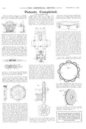
between the driving and driven members of a clutch, the driving cone (a) is provided with openings (b) into which are placed solid pieces of indiarubber (e), which partly project beyond the surface of the cone. Round the cone is arranged a strip of leather (g) in such a manner that the pieces of indiarubber distort the surface of the same. When the cone is moved into contact with the internal conical surface of the clutch, the rounded corners, or projections, on the leather, which touch the former, first slip, and then the slip diminishes, and the engagement gradirtily progresses as the surface tends to les Arne its conical shape, ANTI-SLIP DEVICE. — King. — No. 18,496, dated 15th August, 1907.—Arranged in sockets (3) secured to the axle, are vertical rods (1). controlled by helical springs (2). In the lower ends of these rods are slots (a) adapted to receive a spindle (6). The spindle is free to cant within the slots, and is held in its correct pcsition by springs (c) secured in adjustable studs (d). Upon the spindle (6) a wheel (7) rotates, having a pneumatic or solid tiro (8). To effect the raising or lowering of the wheel (7), the top parts of the rods (1) are connected by a bridge piece (10) which is connected to the bracket (3) by means of pivotal links or toggle joints, (11, 12), and operated by the driver by means of the rod (13). It will be seen that, when side-slip takes place, the wheel (7) with its spindle (6) will cant, as shown
by the chain lines in the figure, thereby bringing the metal edge of the wheel (7) into contact with the road, and in. this way slipping is prevented. SPRINGS FOR MOTOR VEHICLES. —Biissing.—No. 3,385, dated (under Convention) 19th June, 1906.--The leaf spring
(n) resting on the fixed axle (75) is connected, at each end, by straps (d) to a vertical spring-bar (c) mounted in brackets (i). Discs are fixed on the lower end of the spring-bar (e); between these discs and the brackets (1), helical springs (g) are arranged. On the end of the leaf spring which is nearest to the front of the car, a horizontal pair of links (b) is bolted to the spring eyelets (c), on which the straps (d) engage ; the other end of this pair of links is mounted on a part (a) which is pivotally connected with the frame (o). This link transmits a horizontal tension to the frame, and to the leaf spring, and thereby to the axle; it also allows the vertical movement of the frame and the leaf spring eye (e), relatively to one another, which movement is produced by the helical spring (g).
ANTI-SLIP DEVICE.—Pollard and Another.—No. 24,570, dated 2nd Novem
ber, 1906.—Between the twin tires (a) a chain (b) is arranged, to which a series of loops (d) are secured at intervals. A suitable connecting link is provided, consist ing of two hooks (e, f) turned in opposite direction and having a split pin (g) placed in a central position.