


Device for Protecting Tyres
Page 64
If you've noticed an error in this article please click here to report it so we can fix it.
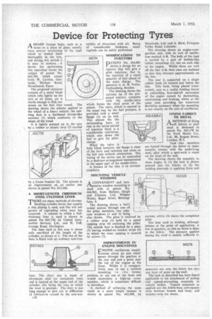
ASHARP foreign body, such as a stone or a piece of glass, usually takes several revolutions of the road wheel to embed itself thoroughly in the tyre, and during this period it is easy to remove.. A device for performing this operation forms the subject of patent No. 662,701, which comes from W. Carlton, Oaklands, Herbert Road, Hornchurch, Essex.
The proposed extractor consists of a metal blade which rubs lightly on the tyre at all times, yet is sturdy enough to flick out stones on the first time round. The drawing shows the scheme applied to the wheel of a heavy vehicle; the rubbing face is a hardened stirrup-like member (1) which conforms to the shape of the tread.
It iS lightly pressed on to the tyre by a rubber or plastic strip (2) carried by a frame bracket (3). The scheme is an improvement on an earlier one shown in patent No. 613,666.
A SHORT-LENGTH CHROMIUMSTEEL CYLINDER LINER
THERE are many methods of chrome'. finishing cylinder bores, but usually a thin plating is used, and this will not permit of regrinding when wear has occurred. A soheme in which a fullthickness liner is used is shown in patent No. 662,738, by United Automobile Services, Ltd., and H. Tuff, Grange Road, Darlington.
The liner used in this case is about only one-third of the length of the cylinder, as shown at 1. The rest of the bore is fitted with an ordinary cast-iron
liner. The short one is made of chromium steel (or chromium iron) and is located at the upper end of the cylinder, this being the area in which the wear is greatest. The-liner is not long enough to give rise to difficulties of lubrication caused by the non-wet
A38 tability of chromium with oil. Being of considerable thickness, many regrinds can be safely performed.
MODIFICATIONS TO
662,701 INJECTORS PATENT No. 664,884 shows a design for an injector that will give a pilot injection; that is. the injection of a small quantity of fuel ahead of the main charge. The patentee is A. B. Volvo, Gothenburg, Sweden.
The drawing shows the extreme tip of the proposed injector, complete with the needle-valve which forms the chief point of the patent. The valve, which is opened in the usual way by the fuel pressure, is provided with a small flange (1) on its end. This almost fits the surrounding bore, so that in the initial period of injection there is a considerable restriction, which cuts down the fuel to give the pilotcharge. When the valve is fully lifted, however, the flange is clear of the bore, and injection can occur at the full rate without obstruction. The timing of the action can be controlled by a dash-pot arrangement incorporated in the upper part of the needle-valve. A feature of the idea is its extreme simplicity.
MOUNTING VEHICLE WINDOWS
ACONVENIENT and inexpensive window mounting is dealt with in patent No. 664,965, from Hallam, Sleigh and Cheston, Ltd., Widney Works, Bagot Street, Birmingham, 4.
The drawing shows a horizontal section through one of the pillar members, two adjacent windows (1 and 2) being also shown. The glass is received by a rubber strip (3) held by a metal capping strip (4) enclosing the pillar. The outside face is finished by a plate (5) having welded-on bracket strips (6) to which the inner capping is secured by screws (7).
IMPROVEMENTS IN ENGINE MOUNTINGS La NGINE oscillations usually occur about an axis whict passes through the gearbox at the rear end and a point neat the top of the engine at the front. Whilst it is comparatively easy to use a resilient mounting i n t h e former position, to use one at the front end would necesSitate a high-up crossmember, which is sometimes difficult to introduce.
'A method of achieving the same result in a more simple manner is shown in patent No. 662,688, by Metalastik, Ltd, and A. Hirst, Fvington Valley Road, Leicester.
The drawing shows an engine-cumgearbox unit, with its axis of oscillation marked A-B. The bulk of the load is carried by a pair of bobbin-like, rubber mountings (1), one on each side of the engine. Whilst these are well off the line A-B, their axes are inclinedso that they intersect approximately on the line.
The rear is supported on a single rubber bush (2) located just below the
line. This bush, being placed transversely, acts as a useful limiting factor in controlling fore-and-aft movement of the engine caused by declutching, accelerating and braking, whilst at the same time providing the transverse flexibility necessary when the mounting is not exactly on the axis of oscillation.
FIXING FABRICS TO METAL
A METHOD of fixing PAsoft fabrics to steel
sheet is disclosed in patent No. 663,178 by the Ford Motor Co., Ltd., 88, Regent Street, London, W.I.
lack like members are forced through the fabric to make metallic contact with the underlying steel, after which a spot-weld is made on the head of the tack.
The drawing shows the assembly in three stages; at (1) the tack is shown pressed into the fabric; at (2) the welding electrode is applying force and current, whilst (3) shows the completed joint.
The heat used in welding, although intense at the point of application, is low in quantity, so that no harm is doneto the fabric. The pressure applied during the weld is usually sufficient to
penetrate not only the fabric but also any layer of paint on the steel. .,
The tack as described has been found applicable to the attachment of sealing and squeak-preventing materials to vehicle bodies. Typical materials so applied are .the fabric-base anti-squeak strip between bonnet and body, and weather-strip for doors.