


PATENTS SUMMARIZED.
Page 22
If you've noticed an error in this article please click here to report it so we can fix it.
Using the Engine as a Brake.
There have been many attempts to use the.engine as a brake, and any well-considered invention to that end has more than usual interest for the designer. For this reason we have selected specification No. 112,644, by the well-known firm, of`Saurer; of . Switzerland, as being the most interesting of those we publish this week.
• It is generally understood that some sort of alteration of the timing is necessary, so that the engine will, during the
. period,of its use as a brake, operate as•an air compressor, and the usual method is to move the exhaust cams. The difficulty with a:Single camshaft is that it is not convenient to move the exhaust cams independently of the induction cams. In the present innovation the camshaft as a Wholeis advanced. 90 degrees. This is equivalent to putting forward the cycle of operations one complete stroke of the engine.
Iii addition, when the power unit, is being used as a brake, the induction • manifold is sealed at the carburetter, and Serves as compression space. With the new setting, the four strokes of the engine become (1) outward stroke, fol.' the .main part with the induction valve closed, is• a suction stroke ; (2) inward stroke, for the main part with both valves .closed, is compression ; (3) °award stroke, with exhaust valve open, is again suctien stroke ; (4) inward stroke, with induction valve open, is a powerful cornpreasion stroke into the induction mani fold.'
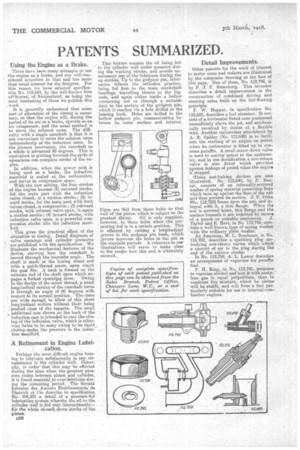
This gives the practical effect of the alteration to timing, Detail diagrams of valve openings and cylinder pressures ' are published with the specification. We • illustrate the mechanical features of the
• device, showing how the camshaft is Moved through the requisite angle. The shaft is made at the timing wheel end with a quick-thread screw, upon which the gear fits. A neck is formed on the extreme end of the shaft upon which engages a forked operatipg lever. Owing to the design of the screw thread, a small longitudinal motion of the camshaft turns it through an angle of 90 'degrees with respect to its normal position. The cams are wide enough to allow of this short longitudinal motion without their being . pushed clear of the tappets. The small ‘, additional cam shown on the back of the induction cam is intended to ease the closing Of the induction valve, which is otherwise liable to be noisy owing to its rapid,
• closing.' under the pressure in the induction 'manifold.
A Refinement in Engine Lubri cation.
. Perhaps the most difficult engine bearing to lubricate satisfactorily in any cir-cuniatanceis the cylinder wall. Generally, in order that this may be effected during the time when the greatest pressure exists between piston and cylinder, it is found essential to over-kibricate during the remaining period. . The Sociate Lorraine des Amiens. Etablissements• de Dietrich et Cie describe in specification No. • 104,331 a detail, of a' pressure-fed lubricating system whereby the oil to,the cylinder wall is fed only intermittently— for the whole ofitach.down•Stroke of the Osten.
050 This feature ensures the oil being fed to the cylinder wall under pressure during the working stroke, and avoids unnecessary use of thelubricant during the up strokes. Up to the gudgeon pin, lubrication follows the orthodox practice, being fed first to the main crankshaft bearings travelling thence ,to the bigends, and again either inside a hollow connecting rod or through a suitable duct to the surface of the giidgeon pin, which it reaches via a hole drilled in the bearing bush. Holes are drilled in the hollow gudgeon pin, communicating between its outer surface and interior.
Pipes are ltid from these holes to that wall of the piston which is subject to the greatest thrust. Oil is only supplied, however, to these holes when the connecting rod is in a certain position. This is effected by cutting a longitudinal groove in the gudgeon pin bush, which groove uncovers the holes in the phi at the requisite periods. A reference to our illustrations will serve to make clear to the reader how this end is ultimately secured..
Detail Improvements.
Other patents for the week of interest to motor users and makers are illustrated by the composite drawing at tho foot of this page. One of them, No. 112,745, is by P. J. F. Batenburg. This inventor describes a detail improvement in the construction of combined driving and steering axles built on the full-floating principle. F. W. Hopper, in Specification No. 112,683, describes a fuel atomizer. It con sists of a horizontal fluted cone positioned immediately above the jet, and mechanically revolved by means of a .flexible wire. Another, carburetter attachment by Af E. Oakley (No. 112,648) is to facilitate the starting of an engine on petrol when its carburetter is fitted up to consume paraffin. A small screw-down valve is used to convey petrol to the carburetter, and in one modification a non-return valve is also fitted which provides , against leakage of petrol when the engine is stopped. 'Three nut•locking devices are also illustrated. No. 112,640, by P. Bax ter, consists tif an internally-screwed washer of spring material possessing flaps which turn up against the flats of the nut and thus prevent its motion. J. F. Duke (No. 112,728) forms Upon the nut, and integral with it, a thin flange. When the nut is screwed home, this flange and the surface beneath it are indented by means of a punch or suitable implement. J. Taylor and E. Hart, in No. 112,743, combine a well-known type of spring washer with the ordinary plain washer.
An American, H. L. Boudreau, in No. 112,752, describes a sparking plug embodying non-return valves which admit a current of air to the plug during the end of the suction stroke: '''V . In No. 112,759, A.' L. Lamar describes an arrangement of vaporizer for paraffin
fuel. ' ••
• F. H. King, in No. 112,741, proposes to vaporize alcohol and mix it with acety
lene gas in equal proportions, then to condense the mixture, which he claims will be stable, and will form a fuel particularly suitable for use in internal-corn-, bustion engines.