


Patents Completed.
Page 22
If you've noticed an error in this article please click here to report it so we can fix it.
Complete specifications of the following patents will be sent to any address in the United Kingdom upon receipt of eightpence per copy at the Sale branch, Patent Office, Holborn, W.C.
"Starting on the Switch."
Robert Bosch.—No. 20,623/11, dated under International Convention 22nd September, 1910; Patent of Addition to 13,691 of 1910.—This specification describes a modification of the method set forth in the earlier patent of starting internal-combustion engines by igniting the mixture which remains in a cylinder, by inserting a trembler, through the medium of a push-button switch. In the ordinary arrangement, the branch of this circuit in which the trembler and switch are arranged is connected in parallel with the interrupter, which is positively controlled from the engine shaft. When the engine on starting closes the interrupter, it short-circuits the trembler, and, although the button may be pressed during several revolutions of the engine, sparks can only be obtained when the mechanicallycontrolled interrupter is open. This prevents back-firing. The disadvantage is that the trembler is short-circuited and will not act if the engine stops when the interrupter is closed ; it is then necessary to insert an auxiliary interrupter in the branch circuit of the positively-controlled interrupter. This arrangement, however, allows a possi
bility of back-firing. According to the present invention the mixture is ignited by the trembler if the interrupter be stopped in the open position and by single sparks produced by a hand-controlled switch when it has stopped in the closed position. The switch is arranged in the interrupter circuit, and is so constructed that on its first movement it breaks the interrupter circuit ; on continued movement it closes it, and on still further continued movement the trembler is brought into circuit for the first time. The illustrations show a diagrammatic scheme of the wiring and the construction of the switch.
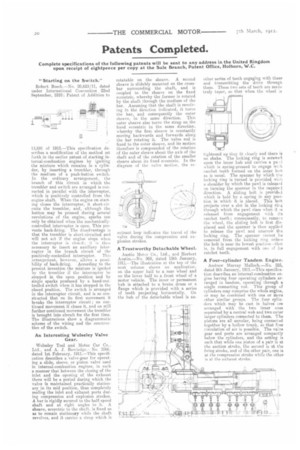
An Interesting Wolseley Valve Gear.
Wolseley Tool and Motor Car Co., Ltd.. and A. J. Roe letiee..— No. 2566. dated 1st February, 1911.—This specification describes a valve-gear for operating a slide, sleeve, or piston valve used in internal-combustion engines, in such a manner that between the closing of the inlet and the opening of the exhaust there will be a period during which the valve is maintained practically stationary in its mid position, thus completely sealing the inlet and exhaust ports during compression and explosion strokes. A bar is rigidly secured to the half-speed shaft and at right angles to it. A sheave, eccentric to the shaft, is fixed so as to remain stationary while the shaft revolves, and it carries a strap which is rotatable on the sheave. A second sheave is slidably mounted on the crossbar surrounding the shaft, and is coupled to the sheave on the fixed eccentric, whereby the former is rotated by the shalt through the medium of the bar. Assuming that the shaft is revolving in the direction indicated, it turns the bar, and consequently the outer sheave, in the same direction. This outer sheave also turns the strap on the fixed eccentric in the same direction, whereby the first, sheave is constantly moving backwards and forwards along the bar rotating it. The valve rod is fixed to the outer sheave, and its motion therefore is compounded of the rotation of the outer sheave about the axis of the shaft and of the rotation of the smaller sheave about its fixed eccentric. In the diagram of the valve motion, the re entrant loop indicates the travel of the valve during the compression and explosion strokes.
A Trustworthy Detachable Wheel.
Austin Motor Co., Ltd., and Herbert Austin.—No. 968, dated 13th January, 1911.—The illustration at the top of the next column shows an application. on the upper half to a rear wheel and on the lower half to a front wheel of a motor vehicle. The inner or permanent hub is attached to a brake drum or a flange which is provided with a series of teeth projecting horizontally. On the hub of the detachable wheel is an tightened up they fit closely and there is no shake. The locking ring is screws4 upon the inner hub and carries a pae-I which is spring-pressed to engage we el ratchet teeth formed on the inner hue as is usual. The spanner by which the locking ring is turned is provided wiOt a shoulder by which the pawl is released on turning the spanner in the requirei direction. A sliding bolt is providel which is held by a spring in any position in which it is placed. This bolt projects over a slot in the locking ring through which the pawl rises when it is released from engagement with its ratchet teeth ; consequently, to remciee the wheel, the sliding bolt is first displaced and the spanner is then applied to release the pawl and unscrew the locking ring. The spanner cannot Fe removed from the lucking ring unless the bolt is near its lowest position—that
is, in full engagement with one its ratchet teeth.
A Four-cylinder Tandem Engine.
Andrew Murray Malloch.—No. 525, dated 9th January, 1911.—This specification describes an internal-combustion engine having four operating cylinders arranged in tandem, operating through a single connecting rod. This group of cylinders may comprise the whole engine, or may be combined with one or more other similar groups. The four cylinders which may be cast in halves are arranged with the two inner ones separated by a central web and two outer larger cylinders connected to them. The pistons are all annular, being connected together by s hollow trunk, so that free circulation of air is possible. The va:ve gear and ports are arranged compactly below the cylinders, and the setting is such that while one piston of a pair is at the suction stroke, the second is at the firing stroke, and of the other pair, one is at the compression stroke while the other is at the exhaust stroke.