


The Gillett-Lehmann Carburetter Attachment.
Page 27
If you've noticed an error in this article please click here to report it so we can fix it.
A Method of Saving 25 per cent. of the Fuel Bill.
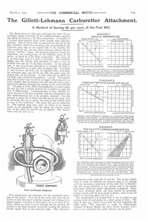
The illustrations on this page and page 620 show the exceedingly simple formation of the Gillett-Lehmann equalising device as fitted to a De Dion carburetter. It consists of a vertical main portion, from which branch three pipe-connections. One of these tubes is connected to the top of the float chamber, whilst the remaining two are attached to the induction pipe, one on the engine side of the throttle, the other on the jet side; the two latter tubes are called by the inventors" balance "pipes. The sectional diagram reveals the disposition and arrangement of the different parts of the device, as fitted to a De Dion carburetter. The body (A) is i inch long, and is inch in diameter. The standard design has the bottom end threaded, so that it can be screwed into the top of the float chamber. In the present case, it was found more convenient to connect the body to the float chamber by a short piece of piping (B). Two tubes (C and D) leave the body (A), on opposite sides, and enter the induction pipe, one on the jet side, the other upon the engine side, of the throttle. A taper plug (E) is fitted into the body, and is held friction tight by , ap (J). The tapered plug has it lower end cut off at an angle, which leaves it at such a length that its extreme end will coincide with a horizontal line passing through the centres of the tubes (D and C). The plug is, also, drilled longitudinally to a point above the cap (J), and a second channel (F) is drilled to meet the first at right-angles. Communication is thus afforded between the air in the float chamber and the atmosphere, but this communication has to be properly adjusted. For this purpose a screw (G) is fitted into the top of the plug, and, by screwing this im or down, the area of the central bore is more or less restricted. The screw (G) can be locked by H. The tapered plug acts, also, by virtue of its bottom .angle, as an adjustable valve by which the relative useful area of the tubes (C and D) can be altered. The throttle valve may be seen at L.
Two adjustments are necessary for the successful operation of the device. First of all the screw (G) must be adjusted so that the engine receives enough fuel to keep it at normal speed : screwing G hard down, so as to close F entirely, allows no petrol to pass through the jet, because the suction in the float chamber caused by turning the startinc, handle equals that in the induction pipe. This illustrates the function of the tubes (B, C, and D). The second adjustment is made by rotating the tapered plug in its seating until the maximum restriction of the tube (C) is effected: this will cause misfiring at low speeds, and is the datum point from which the proper adjustment is obtained. Startingfrom misfiring point, the plug should be gradually twisted round until the best result is shown, when it can be locked by screwing down the cap (J).
The attachment is so simple that it can be fitted to any existing form of carburetter in a short space of time. The price is now .45, which is just half the cost originally decided upon. The apparatus is made by Carburation, i.imited, of Byron House, 85, Fleet Street, London, E.G., and we are informed that quick delivery can be given.