


D. Stewart and Co. (1902), Ltd.
Page 22
If you've noticed an error in this article please click here to report it so we can fix it.
Exhibit :—A Standard 5-ton Steam Wagon.
When the famous Chiswick company, John I. Thornycroft and Co., Ltd., in order that it might devote more time and space to the development of the internal-combustion engine for marine and other purposes, handed over the manufacture of its steam wagons to D. Stewart and Co. (zeoz), Ltd., of Glas gow, it could not have placed the designs into better hands. This Scottish company supplies the whole of Great Britain and the Colonies.
The general appearance of this wagon, and the principles employed in its design, are too well known to need a lengthy description, but a few of its leading features will, perhaps, be appreciated by the motor-wagon user who is contemplating an addition to his "stud." The wagon is designed to meet all the requirements of the Heavy Motorcar Order, and to carry a load of s tons on its own platform, on which there is ample spate even should the goods carried he of a very bulky nature. It is fitted with a fire-tube boiler, of the locomotive type, and specially arranged for convenient stoking from the top through a tunnel connecting the saddleplate with the fire-box crown. It has a large grate-area, and the fire-bars are slung on a hinged frame.
The engine has compound cylinders fitted with balanced slide-valves, operated by a radial link-motion, which gives constant lead and any degree oi linking-up, in both forward and reverse direction, on one eccentric for each cylinder. The cylinders are 4,1, and 7 inches in diameter, for the h.p. and I.p. respectively, and the Piston-stroke is 7 inches. The crankshaft and eccentrics are enclosed in an oil retaining case and lubricated by the " splash" method.
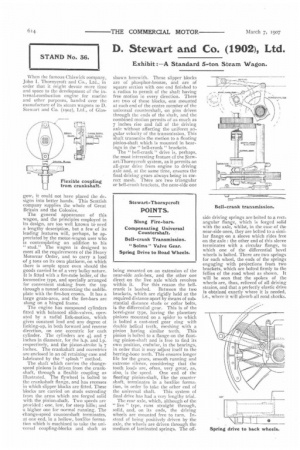
The shaft which carries the changespeed pinions is driven from the crankshaft, through a flexible coupling as illustrated. The flywheel is bolted to the crankshaft flange, and has recesses in which slipper blocks are fitted. These blocks are carried on studs extending From the arms which are forged solid with the pinion-shaft. Two speeds are provided : one, low, for steep hills; and a higher one for normal running. The change-speed countershaft terminates, at one end, in a hollow, boxlike forma. tion which is machined to take the universal coupling-blocks and shaft as
shown herewith. These slipper blocks are of phosphor-bronze, and are of square section with one end finished to a radius to permit of the shaft having free motion in every direction. There are two of these blocks, one mounted at each end of the centre member of the universal countershaft, on pins driven through the ends of the shaft, and the combined motion permits of as much as 7 inches rise and fall of the driving axle without affecting the uniform angular velocity of the transmission. This shaft transmits the motion to a floating pinion-shaft which is mounted in bearings in the " bell-crank" brackets.
The " bell-crank " drive is, perhaps, the most interesting feature of the Stewart-Thornycroft system, as it permits an all-gear drive from engine to driving axle and, at the same time, ensures the final driving gears always being in correct mesh. There are two triangular or bell-crank brackets, the near-side one being mounted on an extension of the near-side axle-box, and the other one direct on the live axle which revolves within it. For this reason the bell crank is bushed. Between the two brackets, which are rigidly held at the required distance apart by means of substantial distance studs or collar bolts, is the differential gear. This is of the bevel-gear type, having the planetary pinions mounted on a spider to which is bolted a cast-steel gear ring with double helical teeth, meshing with a pinion having similar teeth. This pinion is bolted to a flange on the floating pinion-shaft and is free to find its own position, endwise, in the bearings, in order that it may adjust itself to the herring-bone teeth. This ensures longer life for the gears, smooth running and extreme silence, considering that the tooth loads are, often, very great, as, also, is the speed. One end of the floating pinion-shaft, like the counter shaft, terminates in a boxlike formation, in order fo take the other end of the universal shaft. This system of final drive has had a very lengthy trial.
The rear axle, which, although of the " live " type, runs straight through, solid, and, on its ends, the driving wheels are mounted free to turn. Instead of being positively driven by the axle, the wheels are driven through the medium of laminated springs. The off side driving springs are bolted to a rectangular flange, which is forged solid with the axle, whilst, in the case of the near-side ones, they are bolted to a similar Range on a sleeve which rides free on the axle : the other end of this sleeve terminates with a circular flange, to which one of the differential bevel wheels is bolted. There are two springs for each wheel, the ends of the springs engaging with projections from two brackets, which are bolted firmly to the fellies of the road wheel as shown. It will be seen that the spokes of the wheels are, thus, relieved of all driving strains, and that a perfectly elastic drive is obtained exactly where it is needed, i.e., where it will absorb all road shocks.