


OVERHAULING THE PALLADIUM.
Page 25

Page 26
Page 27
Page 28
If you've noticed an error in this article please click here to report it so we can fix it.
No. 17.— Dealing with the YEE and YEE2 4 Ton Chassis. Their Accessibility and Ease of Repair. Adjusting Timken Roller Bearings.
pALLADIUM chassis are builtup from highclass components and embody to a remarkable degree the features of ease of replacement and
general accessibility. Chassis of this make are largely used for omnibus and motor coach work, as well as for the transport of goods, and from advices we have received are giving every satisfaction,
Dismantling. .
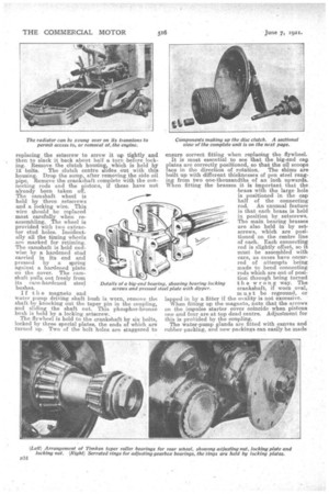
. It is not absolutely necessary to remove the body in order to withdraw all the Units, but in the case of a complete overhaul it may be advisable to do so. Before actually commencing the dismantling of the chassis, it should be thoroughly cleaned down, after which preparations should be made to remove the engine. The water connections must, be broken; next release the radiator stay and the radiator trunnion grip bolts. If the engine is the only unit that has to come out it is unnecessary to remove the radiator completely, as it can then be swung over towards the front. During a complete overhaul, however, it can be dropped completely by unscrew
ing the trunnion nuts, which are split-pinned, after removing the fan pulley and timing cover.
If the radiator only is to be removed, thu timing cover can be left in position and the starting handle taken off. Now, remove the engine support bolts, of which there are two on the front swivel bracket and two in the side bearers; the latter are easily accessible from the side of the frame, Remove the exhaust manifold grip bolt, disconnect the oil pipes and controls, and break the front cardan joint flange, which will be found immediately behind the clutch housing. Before removing the bolt,, it is advisable to tie the cardan shaft to the cross-member above it. Now remove the single bolt of ,the clutch adjuster and swing the pedal stc-n to one side by taking out one of its two bolts. The clutch pedal can then be dropped so that it will pass under the dash, when the engine is lifted by means of suitable tackle.
To remove the front cardan shaft, take off the brass dust-cap and pull the shaft out. If the gearbox only is to come out, undo the flanges of the forward and rear cardan joints.
To take down the gearbox, release the front brake adjustment, remove the three pins from the selector shaft fork ends (these are locked by split-pins only),
wiscrew the nuts from the four suspension bolts, then the trunnion bracket nut. It is unnecessary to remove the footbrake gear as the ..box can be slid forward away from the shoes.
It is advisable to remove the rear axle as a unit complete with its springs. To do this, take out the brake rod fork end pies at the compensator shaft, remove the four spring bolts (at the front end .the nuts of these are inside the frame channels) and jack up the rear of frame, when the axle can be rolled out.
Dealing with the selector box, take off the 'cover and drive out the taper pin holding the selector shaft. Holes in the selector box are provided for this purpose, one being positioned at each side of the shaft so that the pin can be driven in or out.
• Overhauling the Units.
We will take the engine first. On this the timing case cover has already been taken off. Next remove the exhaust and inlet manifolds, and the water pump pipe between the cylinders; remove the latter by unscrewing the holding-down nuts, of which two on each pair of cylinders are under the valve covers. The gudgeon pins are each held by a single setscrew provided with a lock-nut and split-pin. In reassem Laing the greatest care must be exercised when.
replacing the setscrew to screw it up tightly and then to slack it back about half a turn before locking. Remove the clutch housing? which is held by 12 bolts. The clutch centre slides out with this housing. Drop the sump, after removing the side oil pipe. Remove the crankshaft complete with the connecting rods and the pistons, if these have not already been taken off.
The camshaft wheel is
held by three setscrews and a locking wire, This wire ahould he replaced most carefully when reassembling. The wheel is provided with two extractor stud holes. Incidentally all the timing wheels are marked for retiming. The camshaft is held endwise by a hardened stud carried in its end and pressed by a spring against a hardened plate On the cover. The cmshaft pulls out freely from its cases-hardened steel bushes.
I f t Ii e magneto and water pump driving shaft bush is worn, remove the shaft by knocking out the taper pin in the coupling, and sliding the shaft out. This phosphor-bronze bush is held by a locking setscrew.
i The flywheel s held to the crankshaft by six bolts, locked by three special plates, the ends of which are turned up. Two of the bolt holes are staggered to ensure correct fitting when replacing the flywheel.
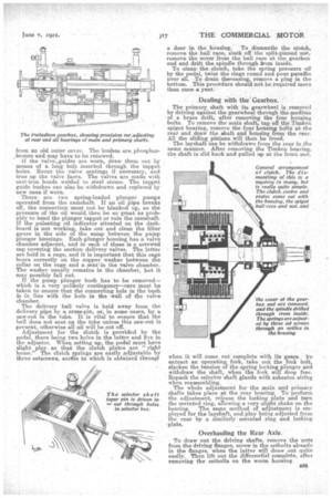
It is most essential to see that the big-end cap plates are correctly positioned, so that the oil scoops face in the direction of rotation. The shims are built up with different thicknesses of pen steel ranging from two one-thousandths of an inch upwards. When fitting the brasses it is important that the brass with the large hole is positioned in the cap half of the connecting rod. An unusual feature is that each brass is held in position by setscrews. The main bearing brasses are also held in by setscrews, which are positioned on the centre line of each. Each connecting rod is slightly offset, so it must be assembled with care, as cases have occurred of attempts being made to bend connecting rods which are out of positioii through being turned the wrong way. The crankshaft, if worn oval, must be reground, or lapped in by a fitter if the ovality is not excessive. When fitting up the magneto, note that the arrows on the impulse starter cover coincide when pistons one and four are at top dead centre. Adjustment for this is proirided by the coupling.
The water-pump glands are fitted with canvas and rubber packing, and new paekings can easily be made from an old outer cover. The bushes are phosphorbronze and may have to be renewed. If the valve.guides are warn, draw them out by means of a long bolt inserted through the tappet holes. Recut the valve seatings if necessary, and true up the valve faces. The valves are made with cast-iron heads welded to steel stems. The tappet guide bushes can also be withdrawn and replaced by new ones if worn.
There are two spring-loaded plunger pumps operated from. the camshaft. If an oil pipe breaks off, the connection must not be blanked up, as the pressure of the oil would_ then be so great as probably to bend the plunger tappet or ruin the camshaft. If the pulsating oil indicator situated• On the dashboard is not working, take out and clean the filter gauze in the side of the sump between the pump plunger housings. Each plunger housing has a valve i
chamber adjacent, and in each of these s a screwed cap -covering the suction delivery valves. The latter are held in a cage, and it is important that this cage bears correctly on the copper washer between the collar on the cage and a seat' in the valve chamber. The washer usually remains in the• chamber, but it may possibly fall out.
If the pump plunger bush has to he removed— which is a very unlikely contingency—care must be taken to ensure that the connecting hole in the bush in line with the hole in the wall of the valve chamber.
The delivery ball valve is held away from the delivery pipe by a cross-pin, or, in some cases, by a saw-cut in the tube. It is vital to ensure that the hall does not seat on the tube unless this saw-cut is present, otherwise all oil will be cut off.
Adjustment for the clutch is provided by the pedal, there being two holes in the latter and five in the adjuster. When setting up, the pedal must have slight play so that the clutch plates are " right home." The clutch ..springs are easily adjustable by three setscrews, access to which is obtained throng}
a door in the housing. To dismantle the clutch, remove the ball race, slack off the split-pinned nut, remove the cover .from the ball race at the gearbox end and drift the spindle through from inside. To cleanthe clutch, take the spring pressure off by the pedal, twist the rings round and pour paraffin over all. --To drain theeeasing, remove a plug in the bottom. This procedure should not be required more than oncea year.
• •
Dealing with the Gearbox.
The primary shaft with its gearwheel is removed by driving against the gearwheel through the medium of a brass drift, after removing the four housing bolts. To remove the main shaft, tap off the Timken spigot bearing, remove the four housing bolts at the rear and draw the shaft and housing from the rear. All the sliding pinions will then be freed. The layshaft can be withdrawrefrom the rear in the same manner. After removing the Timken bearing, the shaft is slid back and pulled up at the front end, when it will come out complete with its gears. 'to extract an operating fork, take out the fork bolt, slacken the tension of the spring locking plunger and withdraw the shaft, when the fork will drop free. Repack the selector shaft glands with asbestos string when reassembling. The whole adjustment for the main and primary shafts takes place at the rear bearing. To perform the adjustment, release the locking plate and turn the serrated ring, allowing a very slight shake on the bearing. The same method of adjustment is employed for the layshaft, end play being adjusted from the rear by a similarly serrated ring and locking plate.
Overhauling the Rear Axle.
To draw out the driving shafts, remove the nuts from the driving flanges, screw in the setbolts already in the flanges. when the latter will draw out quite easily. Then lift out the differential complete, after removing the setbolts on the worm housing To remove the worm wheel, take off the cap nuts, when the wheel can be drapped right out. The differential easing is provided with special books for lifting. To withdraw the worm, release the two clip bolts and locking plate, and unscrew the large slotted nut.
A means of adjustment for centring is provided at each side of the worm wheel, and when making an adjustment the locking plates must first be released and cap bolts slackened ; when the adjustment is correct tighten cap bolts and then replace locking plates. The worm is adjusted at the front end, for which purpose the clip bolts are slackened off and the locking tongue lifted.
Front and Rear Wheels.
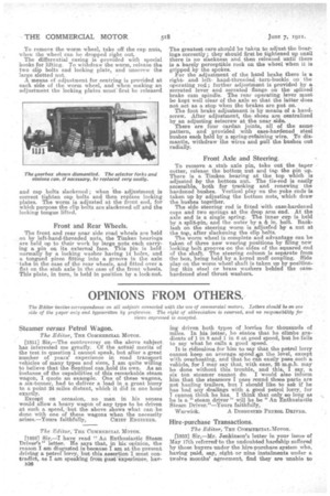
The front and rear near side road wheels are held on by left-hand-threaded nuts, the Timken bearings are held up to their work by large nuts each carrying a pia on its external face. This lain is bold normally by a locking washer having 14 holes, and a tongued piece fitting into a groove in the axle 'tube in the case of the rear wheels., and fitted over a flat on the stub axle in the case of the front wheels. This plate, in turn, is held in position by a lock-nut. The greatest care should be taken to adjust the hearings correctly; they should first be tightened up until there is no slackness and then released until there is a barely perceptible rock on the wheel when it is gripped by the spokes. II or the adjustment of the hand brake there is rightand lefthand-threaded -turn-buckle on the operating rod; further adjustment is provided by a serrated lever and serrated flange on the splined • brake cam spindle. The rear operating lever must be kept well clear of the axle so that the latter does not act as a stop when the brakes are put on.
The foot brake adjustment is by means of a hand: screw. After adjustment, the. shoes are centralized by an adjusting setscrew at the near side. There are four cardan joints, all of the same pattern, and provided with case-hardened steel bushes ea& held by a spring-retaining wire. To dismantle, withdraw the wires and pull the bushes out radially.
Front Axle and Steering_
To remove a stub axle pin, take out the taper cotter, release the bottom nut and tap the pin up. There is a Timken bearing at the top which is adjusted by the bottom nut. The tie-rod is easily accessible, both for tracking and renewing the hardened bushes. Vertical play on the yoke ends is taken up by adjusting the bottom nuts, which draw the bushes together. The side steering red is fitted with case-hardened cups and two springs at the drop arm end. At the axle end is a single spring. The inner cup is held by a aplit-pin, and the outer by a fa in. bolt. Backlash on the steering worm is adjusted by a nut at the top, after slackening the clip bolts.
The worm wheel is complete and advantage can be taken of three new wearing positions by filing new locking bolt grooves on the sides of the squared end of the shaft. The steering column is separate from the box, being held by a keyed muff coupling. Side play on the worm wheel shaft is taken up by positioning thin steel or brass washers behind the casehardened steel thrust washers.