


Patents Completed.
Page 24
If you've noticed an error in this article please click here to report it so we can fix it.
Complete specifications of the following patents will be sent to any address in the United Kingdom upon receipt of eightpence per copy at Sales Branch, Patent Office, Holborn, W.C.
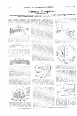
BRAKE-SHOES. — Gallagher. — No. 10,296, dated 12th May, 1908.—This ineention relates to brake-shoes, and it has for its object to provide means whereby the shoe can be completely worn or used up.
The shoe consists of two sections (A, B) east on to a backing (Cr. This backing is of comparatively thick material, and it bus a lug (D) which is reduced in thickness and is provided wits holes (E) whereby it is secured to the, brake key.
The aids of the sections (A, B) that meet are recessed at G and provided with a lug (H) which is adapted to enter the holes (E) provided in the lug of the backing (C). When the shoe is partially worn it may be fitted to a new shoe by drawing the sections (A, B) of the new shoe
apart so as to allow the lug (D) of the partially worn shoe to enter the recess IG) in the new shoe, whereuoon, on bending the sections (A, B) of the new shoe, into place again, the lugs (Hi will engage the holes (G), thereby rigidly securing the same. In this way partially worn brake shoes that have hitherto been scrapieed can be used until they are completely worn out.
SUPPORTING MEANS FOR HEAVY VEHICLES. — Diplock. — No. 26,148, dated 26th November, 1907.—This invention relates to means for supporting heavy vehicles in place of wheels wherein therfs is employed a number of feet which are adapted to he placed successively on the ground as described in the specifications of British Patents Nos. 14,710-99 and 17,502-03 (lliplock). In such a device rollers mounted on spokes carrying feet support a rail or track which in turn sup ports the vehicle. The present improvement consists in the use of a chain or flexible band for connecting the rollers and keeping them in contact with the rail. In the illustration (a, a) are feet which are pivoted to the spokes (b). To each of the spokes (b) is fixed a bracket pa) formed with bearings through which slides a bolt (a) having a bifurcated head in which is mounted a flanged chain roller (o). Between the head of the bolt (a) and the inner bearing of the bracket is a spring lpi which tends to force the bolts outwards, such outward movement being limited by a nut (re). The outer disc (d) is formed with apertures (r) through which the brackets (frn project, and, extending round the several rollers le), is an endless chain (s) of such length that it will draw in all those spokes which for the time being are not pressed outwards by the rail (hi and guide plates or side extensions.
DOUBLE-ACTING INTERNAL COMBUSTION ENGIN E.—Lawson.— No. 26,514, dated 30th November, 1907.— This invention relates to double-acting internal-combustion engines and has for its object to transmit the reciprocating motion of the piston to the crankshaft by means outside) of the cylinder, so that the connecting parts are not subjected to the heat of combustion. The engine consists of two parallel double-acting cylinders (d, e) arranged side by side. Within the cylinders are pistons (a) having a gudgeon pin (c), common to both, of considerable length. The gudgeon pin extends through slots or guideways (f) provided in the cylinders and is connected by means of connecting rods (g), rocking beanie (h) and connecting rods (f) with the crankshaft (k). The rocking beams (h) are connected together by a rod (/).) which extends through curved ,:lots (e that are provided in the crankcase Ise.
HYDRA U LIC BRAKE. Weight. -No. 241, dated 4th January, 1908.—This invention relates to hydraulic-brake mechanism for motor vehicles, wherein the brake blocks are operated by hydraulic rams connected to a common source of fluid pressure. Bolted to the frame of the vehicle (a) is a main hydraulic cylinder (b) in which is a ram (e.) connected to both the pedal lever (d) and the hand lever (e). The cylinder (b) communicates, by means of flexible tubing (II, with a cylinder (g) arranged in close proximity to the brake drums (n). Within the cylinder .(,e) is a ram or piston (h) connected to a lever (i) which in turn is connected with a brake shoe )j). The lever (i) is also pivotally connected with the brake shoe (I) by means of a lever (4 A spring (m) tends to keep the bral4 shoes (1, j) out of contact with the brat drum (a). In applying the brakes il ram (e) is forced by means of the hai lever (e) or pedal (d) ieto the cylind (3) thereby forcing the fluid therein alo the pipes (f) to the brake cylinders C A fluid reservoir (0) is provided, ant' is connected with the cylinder (b). T system of braking is particularly ap: cable for use with front-wheel brakes.
AXLES.—Butler.—No, 6,729, da 26th March, 1908.—This invention reb to axles of the type in which two jc oals are riveted or otherwise securer channel irons, which form the body central portion of the axle. The pres improvement consists in the provisior suitable scats for the springs of vehicle. The journals (1) are provi with extensions (2) of substantial th ness having recesses at each side to commodate the channel irons or gir (3, 4). The top portion (5) of the e) sion (2) is cut away to the level of channel irons so as to form a suitable to which the springs of the vehicle be secured either by a bolt pas through the extension or by straps ing round the guides.