


A Dual-purpose Servo Motor
Page 58
If you've noticed an error in this article please click here to report it so we can fix it.
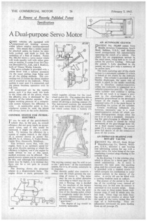
41 Resume of Recently Published Patent Specifications SOME vehicles ate equipped with compressed air braking systems, whilst others employ suction-operated units. This means that a trailer cannot be attached unless its brakes be similarly worked, and tends to limit the versatility of a fleet of trailers. Patent No. 582,361 shows a servo motor which will workequally well with either pressure or suction, it comes from the Clayton Dewandre Co., Ltd., and 3. Rodway, both of Titanic Works, Lincoln.
The servo cylinder is provided with a piston fitted with a tubular extension (1), the usual sealing rings being used on all the sliding surfaces. The connecting-rod (2) forms the thrust member and is attached to the rodwork. When suction is used port 3 is connected, and the piston becomes operative over its full area.
If compressed air be the motive power, port 4 is then used; this leads to the other .side of the piston, where the effective area is decreased by the presence of the tubular member. The higher working pressure of a compression system balances the difference in
area. A noteworthy point is that, whichever system be used, the 'piston will always move in the same direction.
CONTROL SYSTEM FOR PETROLELECTRICS I T can be said of the petrol-electric
vehicle that, in the past, its overall efficiency did not quite reach an economical value, and if this could be increased, it might yet make a comeback. To increase the efficiency by a system of engine control is the object of a scheme shown in patent ' No. 582,359, by A. Glenny, 4, Tudor House, Castle Way, Hanworth, Middlesex.
This inventor states that, with any engine, there is an optimum speed for any given throttle opening at which the efficiency is highest, and if the engine be made always to run at this speed, marked economy can be effected: The petrol-electric system can be arranged to do this, and although the transmission losses may be higher, it is claimed that there can be a net gain in overall efficiency.
The drawing shows the proposed scheme in a diagrammatic form. The engine drives a main generator (1),
The moving contact may be said to act as the " gear-lever " of the transmission system, but it is, of course, automatic in its response.
The throttle pedal also controls a contact arm (8) which governs the running of motor 4. The latter may be run in either direction according to which way the current is flowing; this is decided by the resultant of the battery voltage and the voltage of the generator (3). Thus, the position of the throttle pedal, which is completely under the driver's control, automatically selects the most efficient position of the " gear-lever."
The degree of lag would be scarcely noticeable. AN AUTOMATIC CLUTCH
PATENT No. 5E12,069 comes from • Bendix Aviation Corporation, South Bend, Indiana, U.S.A., and discloses novel arrangements for automatically operating the clutch of a vehicle. The clutch has no engagement springs in the usual sense, being held in or out of action by positive loading. Although the system 's fully described in the patent, we can give only a summary of its action here.
The main operating unit of the clutch system is a pneumatic cylinder (1) which is linked to the clutch by the rodwork shown. The cylinder is provided with a flexible diaphragm, the upper side of which is piped to the intake manifold, and is therefore suction-responsive, whilst the underside is connected to a velocity-responsive port (2). The pneumatic cylinder also contains a spring, and the net result is to impart a pressure to the clutch-plates which is generally proportional to the developed torque of the engine. A solenoidoperated valve (3) is the main factor in controlling the action of the cylinder.
Certain modifying influences are, however, necessary; one is a roadspeed-responsive switch (4) which prevents disengagement except when the car is at or near a standstill. Declutching for gear-changing is effected by a switch (5) which is closed by initial movement of the gear-change lever (6). As a final master icontrol, a normal pedal (7) is also provided. The patent gives full details of all the component parts of the system.
AN IMPROVED BEARING FOR ROTARY VALVES
PATENT No. 582,115, from Briggs Manufacturing Co., Detroit, Michigan, U.S.A., discloses a new bearing and lubricating system for use with a rotary valve, the valve being of the type employing a conical plug rotating in the cylinder head.
In the drawing, 1 is the rotating plug, which is driven by a bevel gear (2) in timed relationship. As it turns it uncovers the inlet port, the sparking plug, and the exhaust port. The piston is provided with a conical crown (3) which compels the combustion to occur almost entirely in the interior of the valve. A cavity (4) can be filled with a cooling medium such aS sodium.
The essence of the patent is the seating of the revolving cone; instead of bearing over its full area its contact is restricted to two narrow strips. Steps in the cone at these points house leadbronze rings (5 and 6) which take the full load. These rings are fully floating, and in use revolve at about half the speed of the valve, rather like the cage of a ball-bearing. They are adequately lubricated via ports leading from an oil passage (7).