 1
1 2
2 3
3 4
4 5
5 6
6 7
7 8
8 9
9 10
10 11
11 12
12 13
13 14
14 15
15 16
16 17
17 18
18 19
19 20
20 21
21 22
22 23
23 24
24 25
25 26
26 27
27 28
28 29
29 30
30 31
31 32
32 33
33 34
34 35
35 36
36 37
37 38
38 39
39 40
40 41
41 42
42 43
43 44
44 45
45 46
46 47
47 48
48 49
49 50
50 51
51 52
52 53
53 54
54 55
55 56
56 57
57 58
58 59
59 60
60 61
61 62
62 63
63 64
64 65
65 66
66 67
67 68
68 69
69 70
70 71
71 72
72 73
73 74
74 75
75 76
76 77
77 78
78 79
79 80
80 81
81 82
82 83
83 84
84 85
85 86
86 87
87 88
88 89
89 90
90 91
91 92
92 93
93 94
94 95
95 96
96 97
97 98
98 99
99 100
100 101
101 102
102 103
103 104
104 105
105 106
106 107
107 108
108 109
109 110
110 111
111 112
112 113
113 114
114 115
115 116
116 117
117 118
118 119
119 120
120 121
121 122
122 123
123 124
124 125
125 126
126 127
127 128
128 129
129 130
130 131
131 132
132 133
133 134
134 135
135 136
136 137
137 138
138 139
139 140
140 141
141 142
142 143
143 144
144 145
145 146
146 147
147 148
148 149
149 150
150 151
151 152
152 153
153 154
154 155
155 156
156 157
157 158
158 159
159 160
160 161
161 162
162 163
163 164
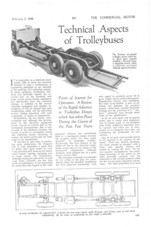
164 Technical .Aspects of Trolleybuses
Page 99
Page 100
Page 101
If you've noticed an error in this article please click here to report it so we can fix it.
IT is impossible, in a relatively short article, fully to cover the technical features of such a combination of .engineering principles as are included in the make-up of a trolleybus chassis. In many instances, mechanical, electrical and hydraulic aspects are involved and, as the electrical side alone covers power-station equipment and distribution lines (the overhead wiring), in addition to the normal vehicular equipment and standby installation, it will be realized that such ramifications really call for individual reviews dealing separately with each component, or group of components.
Nevertheless, all are closely interconnected and, although the development of the electrical equipment clearly exceeds in interest that of the mechanical arrangements, this is only because of the similarity between the layout of petrol or oil-engined chassis and trolleybus chassis, excluding, of course, the motive power and the early stage of the transmission.
It will thus be seen that, in producing early trolleybuses, the designers had in their possession a great deal of tfseful data upon which to work when planning such items as the frame, axles, brakes, steering, springing and, to some extent, the transmission. Although during the past seven or eight N ears fairly 'extensive use has been made of trolleybuses, it can reasonably he stated that this branch of the road
transport industry has contributed little of a mechanical nature towards the progress which has been made generally in passenger vehicles. Accordingly, the chief interest of the trolleybus lies in the electrical installation rather than in the design of the mechanical components, although naturally these subjects are, to a great extent, closely allied.
The foregoing statement is confirmed by the events of the past few years, during which the electrical installation has been improved enormously, both
with regard to available power for a given weight and in detail refinements. Regenerative control, once considered the whim of an idealist, is now, to all intents and purposes, the standard system, whilst more recently rheostatic braking and the provision of a " runback " preventer have become usual items of the specification.
So far we have dealt only in general terms, and it would seem opportune now to review some of the problems With which trolleybus operators have to contend and which are, in turn, passed on to designers when they are considering the production of new vehicles.
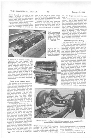
One of the most controversial points of the moment is the position of the motor. There are, broadly speaking, two main schools of thought, with a third, only recently formed, still further to confuse the issue. Of the two popular arrangements, the amidships mounting of the motor is the more generally adopted, but the adherents of the forward position claim for this layout many important advantages. The third possibility is to have
=tors located at the side of the chassis. A vehicle has already been produced which has two side-mounted motors, each being provided with propeller-shaft to drive its appropriate wheels through special gearing.
As we have already indicated, however, the two common positions for the motor are amidships or forward, and it would be as well to consider the arguments for and against both arrangements. The chief claim put forward by the adherents of the central position is that it permits the use of a short propeller-shaft which requires only two universal joints. Furthermore, the accessibility of the motor, fromthe point of view of removal from the frame, is said to be better than when it is mounted in the forward position, because it can be lowered by jacks, into a pit, with comparative ease.
Claims for the Forward Motor.
The sponsors of the forward positiou admit that a motor in the front necessitates a longer transmission line, and more universal joints than in the case of a centrally placed motor, but point out that modern universal joints are reliable and durable. In any case, they emphasize that troubles experienced in the past have mainly originated from the large angles through which the joints have had to work and the difficulty of obtaining constant angular velocity in order to • eliminate vibration.
An advantage claimed for the forward position of the motor is that no restriction is placed on the size or shape of the field coils. With a centrally placed unit, a definite limit is imposed on the shape, and, to some extent, on the size of the fields, in order not to exceed a certain rigidly fixed dimension for floor height. For this reason the number of turns put into the shunt windings is also limited, so that the shunt current is higher in a centrally placed motor than in one mounted in the forward position.
Whilst it is admitted that the forward position is desirable because the motor is well protected from dust thrown up by the front wheels, it is probable that to remove and to replace such a unit would be a longer job 016 than in the case of a chassis having
the motor installed amidships. Indeed, it might be necessary to remove the front cross-member.
Although there are many attractive features in the layout of the dualmotor chassis, in which a power unit is placed on each side of the main frame, there are certain grounds for criticism.
Weight is increased and the cost must obviously be higher than with an -orthodox single-motor system, but from the point of view of accessibility, absence of restriction on floor height, etc., the design has much to commend it.
Now let us consider the question of
control. As we have already indicated, the regenerative system is, today, specified by most operators, and nearly all manufacturers are in a position to supply vehicles thus equipped. There are many features connected with this form of control which ara worthy of mention. Two examples which may be dealt with at some length are the provision of automatic action and the inclusion of a system of wiring that is so planned that tho shunt circuit is never broken.
Improved Regenerative Braking. ,
On some chassis, the driver has to " feel " for the regenerative position of the control pedal, but vehicles are now being operated which give regeneration no matter what action the driver takes. Evenif he remove his foot from the control pedal, regeneration continues down to the cutting-oat speed of about 10 m.p.h.
By maintaining the shunt circuit mahout a break, a big surge of extra high-voltage current is avoided When regeneration commences after the shunt field has been reconnected, consequently the risk of insulation breakdown is minimized. Such a circuit permits a drum controller to be used with a large number of steps. • •
Usually, the load imposed by the 'regeneration of current is sufficient for allordinary braking needs, but below the speed at which regeneration 'ceases rheostatic braking follows, thereby relieving the mechanical brakes of practically all onerous duties. It is true that the rheostatic system does not operate below about 2 m.p.h. and the mechanical brakes have to be brought into operation to bring the vehicle to rest, but by such work no appreciable
heat is developed and it is by no means uncommon for shoe facings to last almost indefinitely.
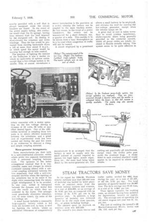
This brings us to " nm-back " preventers. A spring-closed contactor is
usually provided with a coil that is always energized while the circuit breakers are closed. In the event of the power supply failing, this contactor would close (by its spring), having been released from the load imposed by the energized coil.In closing, it short-circuits the armature and series windings. Thus the bus would be prevented from running backwards down a hill at more than about 2 m.p.h., at which speed the, motor would be running fast enough to take control.
The question of lighting the interior of the trolleybus is also a matter on which no uniformity of opinion exists, except that a low-voltage system is desirable. This, of course, necessitates a
rotary converter with a, motor operating on the line voltage driving a dynamo of 12 volts, 24 volts or any other desired figure. One of the difficulties involved in coupling these two units is to obtain effective insulation between the armatures, and a great deal of experimental work has been carried out during the past few years in an endeavour to discover a cheap and simple coupling material.
Motor-generator Arrangements.
Some manufacturers pin their faith to a unit-constructed converter, whilst others prefer two separate instruments with a universal coupling between them. The sponsors of the latter arrangement contend that it is considerably easier and cheaper to obtain continued running silence with a universal coupling interposed between the two armatures, than with a unit-constructed machine where the centring of the armatures has to be exact if the slight whirr emanating from the microscopic misalignment is to be avoided. In any case, rubber is interposed between the dynamo and motor feet and the cradle on which they are mounted in the frame. This arrangement practically eliminates vibration, and, to some extent, the noise of the low-voltage set.
A usual layout includes a reasonably large-capacity battery which is fed from the dynamo and, in turn, is used for lighting the vehicle, whilst an additional refinement of comparatively recent introduction is the provision of a switch whereby the battery can be coupled to the main traction motor. By this means, in the event of a power breakdown, the vehicle can be rnanceuvred for a short distance, say, a quarter of a mile. This enables it to be driven from a busy thoroughfare on to a by-road where congestion of traffic will not be caused.
A circuit employed by a prominent
manufacturer is so arranged that the battery is used to supply only the small amount of current required to operate the legal lights, screen wiper, horn, etc., the main load being taken direct by the motor-generator set. This
allows a small battery to be employe& and obviates the need for running the low-voltage generator, except when the interior lamps are lit A great deal of care is taken nowadays to avoid wireless interference, choke-capacity filters being generally provided in the contactor circuits, whilst all power cables are totally enclosed in flexible metallic tubing. This system seems to be quite effective in
cutting out practically all interference. except when the trolley poles pass under the overhead frogs. A choke fitted to each overhead standard would appear to be required to obtain ideal results.