 1
1 2
2 3
3 4
4 5
5 6
6 7
7 8
8 9
9 10
10 11
11 12
12 13
13 14
14 15
15 16
16 17
17 18
18 19
19 20
20 21
21 22
22 23
23 24
24 25
25 26
26 27
27 28
28 29
29 30
30 31
31 32
32 33
33 34
34 35
35 36
36 37
37 38
38 39
39 40
40 41
41 42
42 43
43 44
44 45
45 46
46 47
47 48
48 49
49 50
50 51
51 52
52 53
53 54
54 55
55 56
56 57
57 58
58 59
59 60
60 61
61 62
62 63
63 64
64 65
65 66
66 67
67 68
68 69
69 70
70 71
71 72
72 73
73 74
74 75
75 76
76 77
77 78
78 79
79 80
80 81
81 82
82 83
83 84
84 85
85 86
86 87
87 88
88 89
89 90
90 91
91 92
92 93
93 94
94 95
95 96
96 97
97 98
98 99
99 100
100 101
101 102
102 103
103 104
104 105
105 106
106 107
107 108
108 109
109 110
110 111
111 112
112 113
113 114
114 115
115 116
116 117
117 118
118 119
119 120
120 121
121 122
122 123
123 124
124 125
125 126
126 127
127 128
128 129
129 130
130 131
131 132
132 133
133 134
134 135
135 136
136 137
137 138
138 139
139 140
140 141
141 142
142 143
143 144
144 145
145 146
146 147
147 148
148 149
149 150
150 151
151 152
152 153
153 154
154 155
155 156
156 157
157 158
158 159
159 160
160 161
161 162
162 163
163 164
164 DESERT TRADITION T(
Page 86
Page 87
Page 88
Page 89
If you've noticed an error in this article please click here to report it so we can fix it.
IMPROVE Bus DESIGN
By L. A. Poole,
M.1.A.E.
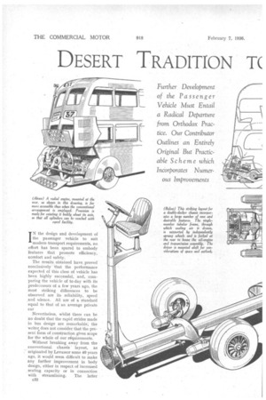
IN the design and development of the passenger vehicle to suit modern -transport requirements, no effort has been spared to embody features that promote efficiency, comfort and safety.
The results obtained have proved conclusively that the performance expected of this class of vehicle has been highly successful, and, comparing the vehicle of to-day with its predecessors of a few years ago, the most striking differences to be observed are its reliability, speed and silence. All are of a standard equal to that of an average private car
Nevertheless, whilst there can be no doubt that the rapid strides made in bus design are remarkable; the writer. does not consider that the present form of construction gives scope for the whole of our requirements.
Without breaking away from the conventional chassis' layout, as originated by Levassor some 40 years ago, it would seem difficult to make any further improvement in body design, either in respect of increased • seating capacity or in connection with streamlining. The latter c32
appears now to be coming into vogue, probably to stay, for, whether it has advantages from an aerodynamic point of view, or. whether it assists fuel economy in lessening headwind resistance, it does undoubtedly add to the appearance of the vehicle, whilst facilitating cleaning and washing down. Body streamlining, however, can properly be achieved only on a chassis designed for the purpose.
The half-width driver's cab, with forward engine position, makes it impossible to present a smooth frontage. Additionally, it is bad Practice on the score Of inaccessibility to cover over the engine. Incidentally, the means for access to the modern engine, when installed in this manner, leaves much to be desired, because the engine is boxed up on three sides, by the radiator, driver's cab and bulkhead respectively, with a liberal width of mud-wing projecting. Under these conditions, engine adjustments and repairs become a matter of gymnastics and patience, and much time is wasted in consequence.
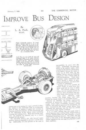
Turning now to the question of
chassis weight, it would seem that much could still be done to lessen this. The forward position of the engine and the rearward position of the final drive necessitate long propeller shafts with bearings and universal joints. Moreover, cross. members, brackets and torque tubes, when used, increase the chassis weight in an incredible manner., Summed up, therefore, the further requirements demanded of present-day chassis are reduction in weight, better engine accessibility, increased seating capacity, and enhanced appearance by streamlining. In these circumstances the writer cannot refrain from expressing his conviction that the time has arrived when current design requires reviewing.
It is, ot course, realized that this would entail a radical departure from existing design, would involve a specially adapted power unit, and, naturally, a layout embodying unorthodox features. The writer, who has made a close study of the many-sided aspects of the subject, submits on the next page his proposals to meet these conditions.
It will be understood that the illustrations are purely schematic and do not represent final design. The distinctive mechanical and other features of the proposed chassis are as follow:— (a) A powerful radial five-cylindered compression-ignition engine with single-sleeve valves.
(b) Cooling by fan and radiators integral with engine.
(c) PreseIective epicyclic gear.
(d) Hydraulic transmission.
(e) Spiral-bevel drive, with cardan shafts.
(f) The mounting of the engine and transmission unit by three-point rubber suspension.
(g) Ease of detachment of this assembly.
(h) Tubular backbone frame.
(i) Independent frontand rear-wheel suspension.
(j) Fan-spoked road wheels.
(k) Oversize low-pressure tyres.
.(1) Streamlined body, with front entrance.
(m) Elevated driver's position.
(n) Exhaust outlet to roof.
The Type of Engine Favoured.
The engine depicted is of the radial compression-ignition type, mainly based on aero lines, having five cylinders with single-sleeve valves and a separate fuel pump, incorporated in the crankcase, for each cylinder. The adoption of this type of engine is chiefly due to its possessing distinct advantages in respect of the power-to-weight ratio, and in the compactness of the crankcase and crankshaft. Incidentally, this type of unit can be given an excellent degree of mechanical balance.
It will be realized that an engine based on these lines has extreme simplicity, being devoid of valve springs, tappets, etc. Furthermore, the absence of an electrical ignition system and a carburetter considerably enhances its immunity from petty breakdowns. The compressionignition engine runs at a lower temperature than its petrol confrere, therefore, the cost and weight of the radiator should be less, whilst it has been proved that the singlesleeve-valve oil engine is capable of far greater power output than is usually obtained from the poppet-valve engine of equal dimensions.
The former type of power unit has also many mechanical and thermo-dynamical advantages over the latter. It allows of complete freedom in combustion-chamber design, and the low fuel consumption of these engines shows that full advantage has been taken of this point. The sleeve is given a rotary, as well as a reciprocating movement, and because it is kept moving continuously and its velocity is almost constant, the lubrication troubles experienced with other types of sleeve valve are absent.
Mr. Ricardo has undoubtedly developed the compressionignition single-sleeve-valve engine to a very successful state, and the Bristol company has built engines on these lines for aero work, with extremely satisfactory results.
It is understood that these engines hays a lower fuel and oil consumption than the corresponding type of poppetvalve engine, also that the maintenance costs are lower. In view of these facts, the radial engine would seem to be ideal for the purpose the writer has in mind.
Ample Cooling Assured.
The cooling of the unit would be assured by separate radiators, accommodated in four of the five spaces between the cylinders. This method possesses the advantage that they may immediately be removed, and new ones substituted. There is a water pump at the bottom of the engine, and this is coupled in tandem with the oil-circulating pump, as illustrated. An hydraulic clutch is provided, upon the periphery of which is mounted a large cowled fan, which impels cold air through the radiator cores, from the inside of the engine compartment, and ensures adequate cooling.
Fresh air is drawn from the front of the vehicle through the main tubular frame member. This has the advantage of also passing cold air over the positively driven dynamo, mounted on top of the gearbox, and thus obviating consequent overheating and loss of electrical efficiency. The starter motor is mounted at the gearbox side.
The unit, comprising the engine, clutch, gearbox and back-axle casing, is mounted at three rubber-insulated points. That at the front consists of a large rubber bush, c34
surmounting the nose-piece on the axle casieg and resting• in a support formed in the tubular frame. The two rear supports carry the bracket bolted to the gearbox immediately before the hydraulic-clutch face.
Two brackets also surround and are bolted to the crankcase. These locate the engine, but are detachable from the gearbox support. By this means the engine can be withdrawn without disturbing the gearbox or axle casing.
The lower cylinders are as easily accessible as those at the top, for the engine can be rotated by means of a steel bar, inserted in lugs on the crankcase, after the securing bolts have been removed and the r-zhaust outlet flange loosened. Owing to the engine being self-contained, this is quite practicable, and the radiators and all units rotate with the engine, the filler caps and blow-off valves being watertight.
In this manner the combustion head of one of the lower cylinders can be detached, without removing the engine from the chassis. The whole scheme therefore offers the utmost accessibility.
In the event of its being necessary to remove the complete power unit, by unbolting the two rear insulated brackets, the whole assembly can be withdrawn.
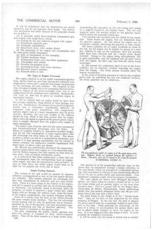
The gearbox is of the preselective epicyclic type, or the power may be transmitted through a torque converter, to the road wheels, which are arranged for independent springing, their movement in relation to the chassis being allowed for by the use of cardan shafts and universal joints. Tyre equipment comprises single ultra-low-pressure pneumatics.
The road wheels are shown with 45-degree fan-shaped spokes, the object being to create a current of air to cool the brake drums and so prevent injury to the tyres from excessive heat. This is a patent held by the Rogers Bros. Corporation of Albion, Pennsylvania, which undertaking claims that this method dissipates brake heat 50 per cent. faster than is the case with a plain wheel.
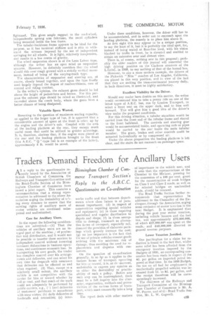
The main frame of the chassis is of the " tubular-backbone" type, on the lines of that originated by the Tatra company of Prague. At the rear end, the fork to support the power unit is built up of pressings, welded to each other and to the tube. These pressings are downswept, in the form of a banjo, to accommodate the cardan shafts, and yet to afford ample strength to carry the engine at the rear. It is not suggested that this design is final. It could probably be cheapened eventually. It will be noted that the frame is forked and is suitably
lightened. This gives ample support to the road-wheel, independently sprung arm fulcrums, the recoil cylinders being mounted inside the box frame.
The tubular-hackbone frame appears to be ideal for the purpose, as it has torsional stiffness and is able to withstand the stresses imposed by the use of independent springing for all wheels. It is light, relatively inexpensive, and results in a low centre of gravity.
The wheel suspension shown is of the Leon Laisnc type, although the writer has an open mind on suspension systems. However, he definitely considers that the wheel should ride over rough ground with a strictly vertical movement, instead of being of the varying-track type.
The characteristics of suspension and steering are, of course, closely bound together, and upon the type finally used largely depend the degree of roadworthiness, ease of control and riding comfort.
In the writer's opinion, the exhaust gases should be led above the height of pedestrians and horses. For this purpose the exhaust pipe should be raised as illustrated, and extended above the coach body, where the gases have a better chance of being dissipated.
Valuable Space Wasted.
Reverting to the question of maximum seating capacity, as applied to the larger type of bus, it is apparent that a considerable amount of space at the front is taken up by the engine and the driver's cab. Coupled with the area of the loading platform at the rear, they occupy much useful room that could be utilized to greater advantage. It is, therefore, obvious that, if the engine were placed at the rear and the loading platform brought to the front (the A.E.C. " Q "-type • bui is an example of the latter), approximately 5 ft. would be saved. Under these conditions, however, the driver still has to be accommodated, and in order not to encroach upon the landing platform, the remedy is to place him above it.
At first sight this may appear to be a unique position, to say the least of it, but it is probably the ideal spot, for, instead of being seated at floor-line level, with his vision blanked by traffic in front, he is elevated and enabled to obtain an extensive near and distant view.
There is, of course, nothing new in this proposal; probably the older readers of this journal will remember the high driving position on the Clarkson steamers of the L,G.O.C. in 1909, to say nothing of that of the horsed bus.
However, to cite a more modern example, the drivers of the Pickwick " Nite " coaches of Los Angeles, California, are placed in this very position, and ia view of the fact that they are making the trans-continental journey daily, in both directions, it must be highly satisfactory.
Excellent Visibility for the Driver.
Should any reader have doubts on this matter, the writer would recommend him to take a penny ride on one of the latest types of A.E.C. bus, run by London Transport, to select a front seat on the upper deck, and to lean well forward. This will give him a good idea of the driver's view under the proposed conditions.
For this driving situation, a tubular stanchion would be carried from the front end of the tubular frame and stayed to the front bulkhead. The controls and steering gear would be accommodated inside, and operating rods or pipes would he carried to the rear inside the main tubular member. The gears, brakes and other controls could be actuated hydraulically or by compressed air.
Under the above proposition the loading platform is left clear, and the stairs do not encroach on passenger space.