 1
1 2
2 3
3 4
4 5
5 6
6 7
7 8
8 9
9 10
10 11
11 12
12 13
13 14
14 15
15 16
16 17
17 18
18 19
19 20
20 21
21 22
22 23
23 24
24 25
25 26
26 27
27 28
28 29
29 30
30 31
31 32
32 33
33 34
34 35
35 36
36 37
37 38
38 39
39 40
40 41
41 42
42 43
43 44
44 45
45 46
46 47
47 48
48 49
49 50
50 51
51 52
52 53
53 54
54 55
55 56
56 57
57 58
58 59
59 60
60 61
61 62
62 63
63 64
64 65
65 66
66 67
67 68
68 69
69 70
70 71
71 72
72 73
73 74
74 75
75 76
76 77
77 78
78 79
79 80
80 81
81 82
82 83
83 84
84 85
85 86
86 87
87 88
88 89
89 90
90 91
91 92
92 93
93 94
94 95
95 96
96 97
97 98
98 99
99 100
100 101
101 102
102 103
103 104
104 105
105 106
106 107
107 108
108 109
109 110
110 111
111 112
112 113
113 114
114 115
115 116
116 117
117 118
118 119
119 120
120 121
121 122
122 123
123 124
124 125
125 126
126 127
127 128
128 129
129 130
130 131
131 132
132 133
133 134
134 135
135 136
136 137
137 138
138 139
139 140
140 141
141 142
142 143
143 144
144 145
145 146
146 147
147 148
148 149
149 150
150 151
151 152
152 153
153 154
154 155
155 156
156 157
157 158
158 159
159 160
160 161
161 162
162 163
163 164
164 Rear-engined Driving Unit
Page 126
If you've noticed an error in this article please click here to report it so we can fix it.
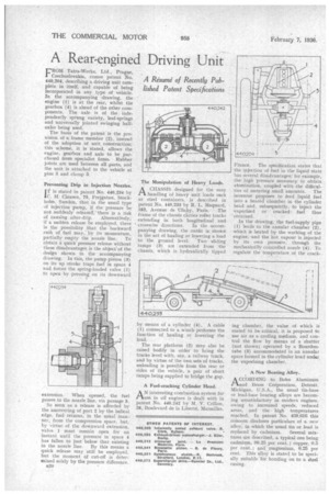
FROM Tatra-Works, Ltd., Prague, Czechoslovakia, comes patent No. 490,204, describing a driving unit complete in itself, and capable of being incorporated in any type of vehicle. In the accompanying •drawing, the engine (I) is at the rear, whilst the gearbox (4) is ahead of the other components. The axle is of the independently sprung variety, leaf-springs and universally jointed swinging halfaxles being used.
The basis of the patent is the provision of a frame member (2), instead of the adoption of unit construction; this scheme, it is stated, allows the engine, gearbox and axle to be purchased from specialist firms. Rubber joints are used between all parts, and the unit is attached to the vehicle at pins 3 and clamp 5.
Preventing Drip in Injection Nozzles.
rf is stated in patent No. 440,234 by
C. H: Clausen, 75, Frejgatan, Stockholm, Sweden, that in the usual type of injection pump, if the pressure be not suddenly released, there is a risk of causing after-drip. Alternatitrely, if a sudden release be employed, there is the possibility that the backward rtith of fuel may, by its momentum,
partially empty the nozzle line. To obtain a quick pressure release without these disadvantages is the objectsof the design shown in the accompanying drawing. In this, the pump piston (3) on its up stroke traps fuel in space 4 and forces the spring-loaded valve (I) to open by pressing on its downward
extension. When opened, the fuel passes to the nozzle line, via passage 5.
So soon as a release is afforded by the uncovering of port 2 by the helical edge, fuel returns, in the usual man-. ner, from the compression space, but, by virtue of the downward extension, valve I must remain open for an instant until the pressure in space 4 has fallen to just below that existing in the nozzle line. By this means a quick release may still be employed, but the moment of cut-off is determined solely by the pressure difference.
B20 The Manipulation of Heavy Loads.
ACHASSIS designed for the easy handling of heavy unit loads such as steel containers, is described in patent No. 440,233 by R. L. Maquard,
183, Avenue de 'Clichy, Paris. The frame of the chassis carries roller tracks extending in both longitudinal and
crosswise directions. In the accompanying drawing, the outfit is shown in the act of hauling or lowering a load to the ground level. Two sliding ramps. (3) are extended from the chassis, which is hydraulically tipped
by means of a cylinder (4). A cable (I) connected to a 'winch performs the function of hauling or lowering the load. ' • The rear platform (2) may also be raised bodily in order to bring the tracks level with, say, a railway truck, and by virtue of the two, sets of tracks, unloading is possible from the rear or sides of the vehicle, a pair of short ramps being supplied to bridge the gap.
A Fuel-cracking Cylinder Head.
AN interesting combustion system_ for use in oil engines is dealt with in patent No. 940,242 by M. V. Crillon, 28, Boulevard. de la Lilaerte, Marseilles,
France. The specification states that the injection of fuel in the liquid state has several disadvantages; for example, the high pressure necessary to obtain atomization, coupled with -the difficulties of metering small amounts. The inventor proposes to feed liquid fuel into a heated chamber in the cylinder head and, subsequently, to inject the vaporized or cracked fuel thus obtained.
In the drawing, the fuel-supply pipe (1) leads to the annular chamber (2), which is heated by the working of the engine, and the hot vapour is injected by its own pressure, through the mechanically controlled nozzle (4). To regulate the temperature of the crack ing chamber, the value of which is stated to be critical, it is proposed to use air as a cooling medium, and control the flow by means of a shutter (not shown) operated by a Bourdontube (3) accommodated in an annular space formed in the cylinder head under the vaporizing chamber.
A•New Bearing Alloy..
ACCORDING to Bohn Aluminum and Brass Corporation, Detroit, Michigan, U.S.A., the usual tin-base or lead-base bearing alloys are becoming unsatisfactory in modern engines, owing to increased speeds, reduced areas, and the high temperatures reached. In patent No. 439,610 this concern discloses particulars of a new alloy, in which the usual tin or lead is replaced by cadmium. Several mixtures are described,.a typical one being cadmium, 99.25 per cent.; copper, 0.5 per cent. ; and' magnesium, 0.25 per cent. This alloy is stated to be specially suitable for bonding on to a steel casing.