


PATENTS SUMMARIZED.
Page 22
If you've noticed an error in this article please click here to report it so we can fix it.
Radiator Regulator.
In order to be able to control the temperature at which the engine works, Mann, Egerton and Co., Ltd., and A. B. Drummond propose to regulate the amount of air passing through the radiator. They do so by disposing before the radiator a shutter which operates on the same principle as the well-known iris diaphragm. It is carried by a central plate in front of the radiator, and opens out against a light framework. Our drawing shows it in its two extreme positions., and the patent (No. 112,226) covers means of operating ,the shutter from the driver's seat.
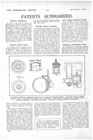
Unusual Speed Gears.
An unusual style of gearing is described in patent No. 112,189, by H. G. 0. Robinson. Each gearwheel has a number of transverse semi-circular grooves cut into its periphery, and engagement as between one wheel and an
other is effected by allowing balls to drop in between each wheel, the semicircular grooves engaging with these balls.
The drawing is diagrammatic. It will be noticed that a tube surrounds the large gearwheel, which tube has an opening at that side at which its companion wheel engages. The tube is filled with balls, and, as the gears revolve, these balls follow one another, leaving one end of the tube, dropping into the recess between the gears, serving to transmit the motion and then falling into the other end of the tulle. The gear is dish engaged by eating abs stream of balls. A by-pass, with a iarger ball arranged as a spring-backed non-return valve, allows the superfluous balls to digress from the main tube when disengagement takes oleos,. Movement of the change Speed
C52 lever to the engaged position releases these side-tracked balls, which then pass again, into circuit.
Oil-filled Shock Absorber.
The absorber described by M. N. Knudson, in patent No. 112,244, is of the type wherein an oil-filled dashpot damps the vibration of the main road springs. An inverted cylinder is placed within a casing, and between cylinder, and rasing are twe passages. One, which may be noted at the bottom of the cylinder, is constant in area; the other, near the top, is adjustable by means of a setscrew.' The piston in the cylinder is provided with a. valve, which allows fairly free passage of the liquid in an upward direction, but none downward. A ball end, is formed on the bottom of the casing, and a similar one on the top of the piston rod. These are coupled respectively to the axle and...vehicle frame.
When the wheel strikes an obstacle, the casing is forced upwards, and move meat of the spring is only restrained to an extent due to the natural viscosity of the fluid, which in the circumstances passes upwards through the valves in the Piston. A violent rebound is prevented by the oil having to pass throUgh the orifice near the top of the cylinder, and the area of that orifice can be readily adjusted if thought desirable by means of the screw plug shown in the drawing abeve.
Aero Engine Cylinder Design.
This invention concerns that type of cylinder in which a light metal, like aluminium, is cast, or otherwise secured about a lining of steel or other hard wearing material. As constructed,the lining is made to servo for the 'inside of the combustion chamber and the valve seatings, as well as for the bored partion.of the cylinder. It may be made in two or more parts. The two parts are then welded together, and the body of the cylinder, including the water. jacket, cast around them. Other construction* are covered. The patentee is S. S. Guy and the specification No. 112,132.
Balanced Carburetter Float;
In carburetters of the, type wherein direct communication exists between the upper part of the float chamber and the mixing chamber, unbalanced pressure on the needle valve exists, owing to the fact that on the under side of the needle is atmospheric pressure plus the weight of the petrol, as against the engine suction which obtains within the fleet chamber. F. Smal corrects the failing named by causing the cover of the float chamber to be made an air-tight fit. The needle valve spindle is prolonged and fits a long bored hole in that cover. The prolonged portion is made the same diameter as the hole below the needle valve. With gravity feed this construction is sufficient to prevent the operation of the needle valve being affected by variations of pressure in the float chamber. Where the fuel_ is pressure fed, it is necessary to cover the upper end of the needle valve, and effect communication, by means of a pipe, between the top of the needle and the inside of the . i
petrol tank. The specification s num
bered 112,150.