


A COMBINED FRICTION AND EPICYCLIC GEAR
Page 30
If you've noticed an error in this article please click here to report it so we can fix it.
A Résumé of Recently Published Patents.
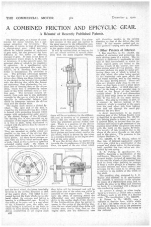
The friction gear, as a means of trans. mission for motor vehicles, has a perpetual attraction for inventors: The chief aim, of course, is that of providing, a change-speed gear, which not only affords an infinite number of variations of gear ratio, but also presents the least difficulty to the driver in effecting changes of gear. If there is one form • of transmission which rivals it, in the eyes of inventors; it is the epioyclic gear, the principal elaim.of which is its simplicity of operation. In a specification with -which -we are concerned this week, No. 152;7'71, by F. Rawling, both of these forms of transmission are embodied in one. T'he principal advantage appears to be that there is no necessity for the driven discs (there are three incorporated in the design) to be brought into contact. with the driving disc while the former are stationary, thus eliminating the con' stant fear of forming flats on the driven discs, which fear Is perpetually before users of the most common form of fric
tion gear. The inventor obtains immunity from such risk in this particular example by the use to which he puts an epicyclie or differential balance gear which he interposes between the driven discs and the cardan shaft, The engine shaft carries a dished flywheel. The open end of the dish is closed by the friction-driving disc, which is formed with projecting tongues which engage with oorresponding axial grooves in the dished flanges of the flywheel. The driving disc is also mounted on an extension of the engine shaft, upon which it is free to slide, being maintained in contact with the driven discs by means of a coil spring. The driven discs are three in number. They are mounted on shafts which. are parallel to the face of the. driving disc, and each shaft carries at its inner end a bevel pinion. All these bevel pinions en. .gage with one bevel wheel mounted upon a bush, which is free to revolve upon the
extended engine shaft. By reason of the relative positions of the bevel pinion's and the bevel wheel, the latter invariably revolves in the reverse direction to that of the engine shaft. The latter is prolonged beyond the bush which carries the bevel wheal, its extreme end taking a bearing in a, differential case. Keyed to the shaft at its outer end is a sun, wheel of the differential gear, the other sun wheel facing it is secured to the bush, to which we have already referred, which is driven contrariwise to the engine shaft )320
by means of the friction gear. The planetary pinions of this gear are carried in the usual manner by the differential case. and the latter transmits the torque direct to the carda,n shaft of the chassis.
It will be realized that, so long as the two sun wheels revolve in' reverse directions with the same singular velocity, there will be no tende cy•for the differential.ease to revolve or to transmit any power; the sun wheels will merely re• volve the planetary pinions within that case. There is a position of the driven discs relative to the face of the driving disc when this condition holds. In that position the driven discs, through the bevel pinions and bevel wheel, revolve the sun wheel, which is driven by the latter in a contrary direction to the engine shaft and at the same speed.
If now the driven discs be moved out towards. the circumference of the driving discs, the speed of the sun wheel which
they drive will be increased and will be more than that of the other one which is attached to the engine shaft. This will have the effect of carrying round the differential case and transmitting the drive to the carda,n shaft of the ehassis. If the friction-driven discs be moved in nearer to the centre of the driving disc; then the sun wheel 'which they drive will revolve more slowly than that on the engine shaft, and the differential case
will, therefore, revolve in the reverse direction to that of the driven disc situ wheel In this manner neutral and reverse gears of varying ratio are afforded.
A Other Patents of Interest.
Kec describes, in No. 131,004, the method of enclosing and protecting the main driving gears of a tractor. The invention is particularly applicable to that type of final transmission in which internal cogged gears are bolted to the driving wheels of the tractor, and with thern engage small driving pinions. This inventor encloses the gears by metal protecting discs, one of which is bolted to the road wheel, the ether being carried by the stationary axle upon which the road wheel revolves, and by the bearing for the main driving pinion. These two -discs are brought quite close to one anOther, so that there is only a small space between their edges. A third disc, however, in the form of an annular ring, is bolted to the flange of the internal. toothed wheel. It is of such dimensions that its inner edge comes as close as possible to the boss of the main driving pinion. This ring is intended, in part, as a retainer,to prevent leakage of tho lubriCant, which is supplied to the gears from the road wheel side from leaking over and out through the small gap between the two discs.
A detail improvement to an engine starting gear of the Eclipse Bendix type is deseribed in specification No. 140.747. The -driving pinion is fitted, as usual. on 'a screwed shaft,' so devised that the preliminary movement of the armature of the starting motor slides this pinion into mesh with the teeth on the engine flywheel. The 'novelty of this invention lies in the shape of the screw threads on the shaft and in the pinion. The patentee is the Eclipse Machine Co.
No. 152,847, by M. Schein, 'refers to that type of internal-combust ion engine valve gear which is a combination of the poppet and piston valve. In the-arrangement specified the two valves are controlled by one spring.
E. R. Palling, in specification No. 152,871,describes a modification of the well-known Timesaver tractor. In the present design, instead of removing one of the smaller wheels of the tractor from back to front whe.n desiring to convert it froma motor plough to a tractor, the inventor removes one wheel entirely, and arranges for the other to be swung into a position in the middle of the width of the shaft.
The sparking plug, designed bv S. E. Taylor and referred to in specification No.. 152,889, is attached to the cylinder by means of a bayonet-type joint, and, to enable the plug to be fitted and removed by hand, it is provided with a flange of non-conducting material.
To connect. 'a plough or other implement to a tractor, J. Pulch uses a couple of flanges, each in the form of a. Maltese cross.— The specification is No. 152,870.
.Harter, in No, 142,071, uses a radiator -of annular form, within which is a fan ; the latter draws air in at its centre and drives it out at the perimeter through the spaces between the tubes of the radiator.