


THE ELECTRIC COMMERCIAL VEHICLE.
Page 10
Page 11
Page 12
If you've noticed an error in this article please click here to report it so we can fix it.
Details of the Construction of the Accumulator ; Descriptions of Characteristic Vehicles. (Concluded.)
By "Chief Engineer."
LAST WEEK I outlined the advantages and disadvantages of the elettrie and its most satisfactory sphereof activity. This week I will deal with the relative advantages of the two types of storage batteries and with thedesign of representative typea of vehicles on which they are employed.
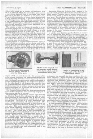
When the electric vehicle was first built in this country many years ago, it.suffered from two principal evils, which were responsible, for its not making more headway, and eventually being relegated to the scrap heap. One of these ills was due to over enthusiastic and, unfortunately, ignoranttsalesmen, who tried to sell them for duties for which they were totally unfitted, and the other was the want of a suitable battery that would withstand road shacks and the strain of heavy charges and discharges. Both of these serious defects are things of the past. The Edison accumulator is, fearmed of nickel and steel elements, or plates, specially constructed to withstand shocks, and is filled with an alkaline electrolyte. It is extra,ordinarTly robust, and will stand charging. at high rates of current without damage. It is high in first cast, but has a long life, and the makers give a very substantial . guarantee. The voltage is slightly over one volt per cell when fully charged, and usually 60 cells are fitted, so that the voltage of the complete battery is 60 to 65 volts. Its internal resistance is rather higher than a lead battery, consequently it requires more energy to charge it for a given mileage output than a lead battery of a similar mileage capacity, and, also, when a heavy demand for current is made, this higher internal resistance naturally tends to cause a, greater drop in volts at the terminals, consequently a vehicle fitted with a steel nickel battery will generally be found rather slow on hills. It is, howev'er, extremely simple, and is easily attended to by even inexpert drivers if ordinary common sense is used. ..
The Ironclad Exide battery is our old friend the lead plate battery, specially, and very successfully, designed for use with battery vehicles and other duties where vibration and he.i.vy 'discharges have to be withstood. The lead plate batteries, as fitted years ago, would not stand vibration, with the result that the paste fell out, and, lying at the foot of the cells, caused short circuits, and greatly reduced the life and efficiency of the battery. Further, the heavy discharges inseparable from road transport work caused the plates to buckle. Added to this was the enormous weight of these old-fashioned batteries which added greatly to the non-paying load.of the vehicles. Manufacturers, therefore, had these threedefects to overcome, and they have been mastered so completely that to-day a robust lead battery is to be had for transport vehicles that will withstand road shocks, can be charged and discharged to almost any extent without injury, and is relatively very light in weight. This has been accomplished •by the Chloride Electric Storage Co., Ltd., amongst others. The materials employed in the Ironclad Exide battery are similar to the ordinary lead plate battery, but the positive plates are specially constructed. . t • 3 ring to sketches on page 563, it will be seen that although the plates are flat, they are constructed in an entirely different manner from the ordinary pasted flat plate. Each plate consists of a number of vertical rods joined at both ends by a horizontal bar. Each rod contains a, lead core, which is surrounded by the active material, and the whole is enclosed in a hard
rubber tube which has a number of horizontal slits cut in it, through which the electrolyte galas access to the active material, but at the same time these slits are so fine that the material is not washed out. The general construction of these plates is calculated to give sufficient elasticity to prevent buckling on a rise of temperature At B is shown a section of one of the rods complete; this is self-explanatory ; A is an assembled positive plate, whilst C is an enlarged section through a positive plate with a separator and a negative plate at either side.
The number of cells in a battery is usually 42 to 44, and as the voltage per cell is about 2.0 or rather over, therefore it follows that the total voltage of a fully charged battery is from 85 to 90 volts. This is coneiderably higher than the voltage with the nickel steel battery, and must -be taken into account when the vehicle is ordered, as the design of the motor depends upon the battery which is to be used. Not only must the voltage be considered, but the characteristics Of the battery must also be known.
There is little to choose between the two types of battery, both are excellent and are doing most satisfactory work all over the country where electrics are employed, and have been -doing so in America far many years. In first coat the Edison is much in excess of the lead battery, but as a set off the life is much
longer. Both are entirely robust. On account of its lower internal resistance the lead battery seems more suitable for hilly districts, because the heavy demands• m€4 with in such work are more readily responded to by the lead battery than by the nickel-steel battery. On the other hand, it will be generally conceded that the attention required by the latter is rather less than by the former, but in neither instance is it exacting, and in both cases can be carried out by any one with ordinary intelligence and care.,
The following illustrations and descriptions of some of the makes of vehicles more commonly employed in this country may be of interest.. On page 562 we illustrate an electric lorry built by the General Vehicle Co., of America, who are now manufacturing in this country, and it will be noted that the general construction is carried out on the following lines. The frame is of a very simple and rigid construction, consisting of rolled channel. The motor, which is entirely enclosed, is slung from a bar supported by the side channels, slightly in front of the lead. axle. This motor drives forward to a counterhaft, which contains a differential gear. The type of drive employed is a Morse silent chain running in an oil bath. On either end of the countershaft are sprockets, from which the hind wheels are driven by means of silent chains. A series wound motor is employed. Internal-expanding shoes are fitted to the rear wheels and controlled by a pedal; • this is the running brake. An emergency brake of the contractoing type is fitted at each end of the countershaft ; machines fitted with either Edison or Ironclad Exide batteries can be supplied. The controller .is of the continuous drum type, having five forward speeds and two reverse. The general construction of the machine is very straightforward and substantial, and it has done much good work. Ransomes, Sims and Jefferies, Ltd., makers of the Orwell vehicle, pin their faith to the two motor design. Their smaller vehicles have a motor fitted to -each front wheel, which is driVen by means of an internal spur gear. For the heavier vehicle, a separate motor drives each hind wheel and is slung on to the side frames. some of the advantages claimed for the two motor design are that it obviates the lase of a differential gear, each rear wheel being driven separately and independently, also that the motors aee more accessible for inspection. Should there be a breakdown of one motor, it is possible, with care, to drive home with onearnotor only, whereas with a single motor design, if the motor sustains damage, it is necessary to be towed home.
It will be seen that the speed reduction is carried out by employing spur gearing combined with the• motor and sAf-contained, making a very compact arrangement. The final drive from the second shaft to the hind Wheel is by silent roller chains. The battery equipment usually supplied is the Ironclad Exide.
The controlling drum consists of two portions, -viz., a main drum and a controlling auxiliary drum. The former is operated by a gate change lever mounted beside the driver, while the latter is -controlled by a pedal. Four forward speeds are provided, and one reverse -Combined with the controller is a starting resistance, but normally the two resistance steps are short circuited. Before moving the controllerfrom one position to another on the main drum, the pedal operating the auxiliary drum must be depressed, which inserts the. two resistance steps into the circuit and, finally, when fully depressed, interrupts the current. When this is accomplished bheanain controller may be adjusted without causing any sparking, as the brushes pass from one segment to another ; after this has been carried out, the-Tedal is allowed to return to its normal position and the circuit is re-established. By this means all sparking is confined to the auxiliary drum, which is protected, so 'far as possible, :by a magnetic blow out, and in any case the segments are quite easy and inexpensive to renew.
Two brakes are fitted, both of which act directly on'. the hind wheels, which is a good point. An illustration of this vehicle appeared last week. A very interesting design of electric vehicle is that built by Electromabile, Leeds, Ltd. This company also specialize on a two-motor drive. The motors are built into the rear axle, and the power is transmitted to the rear wheels through a very ingenious arrangement of spur gearing. One illustration on this page shows the general arrangement of the rear axle, and the other illustrates the design of the gearing.
An examination of the illustrations will be found • ieteresting. It will be,noted that the frame work of the rear axle consists of two parallel rolled steel sections, connected at either end by, and rigidly bolted to, east steel geareases, in which run the special arrangements of gears. Pads for the rear springs are formed on the cast steel gearcases, and one side of the ease is extended to form the axle spindle, The inner side of the ease is designed so that the motor
can be bolted thereto, and will be lineable with the gears contained therein. It will be noted that inside each gearcase are three double gears, each consisting of a large and small spur Pinion mounted on studs, which are in one piece with the driving shaft. This driving shaft passes through the axle spindle and connects with the outer end of the wh-eel hub through the hub cap, which is made of steel. Inside the gearcase an internal gear ring will be observed. When the double pinions are placed on their respective studs all the small pinions engage with this internal spur gear. The driving shaft has no bearing in the axle spindle, the driving gears and driving shaft being supported and held in their correct positions as follow. The double spur gears each have a cylindrical extension, formed on their inner or small end, exactly equal to the pitch diameter of the. small gears. These extensions take their bearing and are supported in a cylindrical track, the diameter of which is equal to the pitch diameter of the internal spur ring. It will, • therefore, be seen that these three points of bearing form a perfect rolling support for the inner end of the driving system the outer end of the driving shaft being supported :tad held, central by the hub cap. When the three gears are in place, the motor can be asse.mbled, and it will be found that the small spur gear fixed to the motor spindle will mesh with the three large gears. The arrangement is extraordinarily compact and simple.
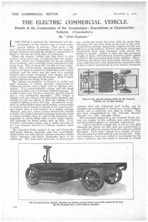
The controller is arranged to give four speeds forward and one reverse. An illustration of this vehicle also appeared last week. The Garrett electries are illustrated. in the large views. These vehicles are of the single motor type. A series-wound enclosed motor is fitted, which has an overload capacity of 300 per cent, for short periods. It is slung from a bar fixed to_ the frame channels slightly in front of the rear axle, and drives forward to a countershaft, which contains the differential gear. This first transmission is by a, silent chain, which runs in an oil bath, and is enclosed in an oil-tight case. The spindle of the motor is fitted, with an oil-throwing device, which prevents any oil leaking from the chain case into the motor. In time, a certain amount of stretching and wear tends to lengthen the chain, but provision is made for it to be tightened by adjusting a radius rod fixed between the motor easing and the countershaft easing which forces the motor further from the countershaft, or allows it to be brought nearer according to requirements, the motor moving round the suspension bar as a. centre_ In order to ensure the easy running of the countershaft, and to prevent any possibility of Undue friction arising through movement in the main frame, the countershaft casing is carried in ball and socket suspension brackets. All the wheels are fitted with Timken roller bearings, and either ball or roller bearings are employed throughout the whole machine, with a view to reducing friction to the lowest possible limit. That this has been successfully accomplished may be gathered from the fact that the power required to revolve the whole mechanism at a speed equal to a road speed of eight miles per hour is only about .3 electrical horse-power input to the motor.
Two independent brakes are fitted, both acting directly on the rear wheels. A foot brake is employed for ordinary running, and this is of the contracting type acting upon the external surface of drums fitted to the rear wheels. The emergency or hand brake is of the expanding type, and acts upon the. internal surfaces of the same drums.
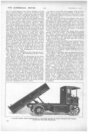
The battery usually provided is the Ironclad Exide, but Edison batteries can be fitted if required. They are placed in an underslung chamber fixed about the middle of the frame. The chamber is provided with doors which act, when open, as platforms, so that the batteries an be withdrawn during charging and when .adjustments are required, which work can then be carried out in comfort.
The vehicle is provided with six forward and four reverse speeds. The controller handle is attached to . the steering column in a convenient position and operates the controller placed in the driver's cab beneath the footboard. The controller embodies certain features which are of interest, and is fitted with the Garrett-Pratt patent trip gear, which is so designed that as soon as the foot or hand brake is. applied the controller automatically returns to the neutral position. This makes it impossible to start the' vehicle except from the neutral position of the controller. Neither can it be started unless the brakes have been released, which prevents a heavy rush of current through the battery and motor, as would hap. pen if this were attempted by a negligent driver. This feature in the design obviates the risk of accidents arising from a sudden. forward movement of the vehicle, which might be caused on releasing the brakes by an independently-operated controller not being placed in the neutral position when the brakes are applied.