


Compensated Torsion-bar Suspension
Page 58
If you've noticed an error in this article please click here to report it so we can fix it.
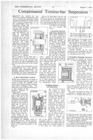
PNo. 693,275 (H. Van Doorne, Deurne, Netherlands), deals with a torsion-rod suspension system intended particularly for vehicles which have to-traverse rough ground. It is of the compensated type, that is, an Obstruction lifting one wheel will put the opposite one down, and thus maintain total stability.
The drawing shows in plan and elevation the form of construction employed. Each wheel is carried by a pair of swinging arms (1) each of which is secured to a cross-tube (2). Inside each tube is a torsion rod which is fixed to the tube at the outer end only.
A central box (3) receives the tube ends and the torsion-bar ends and links them in such a manner that a reversal of movement' is effected; that is rotation of one upper arm "3 transmitted in a reversed direction to the lower arm on the opposite side. This ,gives not only compensation, but also the spring effect due to the torsion rods.
The patent gives full details of this interconnecting box, both diagrammatically and constructionally. Art advantage claimed is that in the event of damage, the whole suspension unit can be quickly removed and replaced.
[693222
A SELF-ADJUSTING TAPPET
THE latest proposals in the design of self-adjusting hydraulic tappets are shown in patent No. 692,886, which comes from General Motors Corporation, Detroit, Michigan, U.S.A. The chief point is the means for allowing air or gas trapped in the
hydraulic chamber to escape readily.
Referring to the drawing, 1 is part of the cam and 2 the end of the push-rod. The tappet has a cylindrical sliding body, the lower end of which touches the cam whilst its upper part is bored to receive a piston. Oil under pressure from the lubricating system arrives via port 3 and reaches the interior via hole 4 and a one-way valve (5).
The whole of the interior is oil-filled and in the unloaded state spring
6. elongates the assembly while oil passes the ball valve. On the upstroke,
the oil trapped in space 7 transmits the thrust to the piston and thence to the push-rod.
692,886
Any air or other gas in the oil will collect in the top of the interior, and can escape during the unloaded periods out of a small vent (8) under the pushrod. The whole assembly is encouraged to rotate by offsetting the cam, and this is believed to centrifuge any air towards the centre.
A SEALING DEVICE FOR BALL BEARINGS' TO retain lubricant in a ball or roller bearing is the purpose of a sealing device shown in patent No. 693,222, by C. Whittle, 65 Chandos Avenue, London, N.20. A feature of the scheme is its compactness.
iii
RUBBER SPRING ANCHORAGES
ASUSPENSION
system in which rubber blocks are substituted for the usual shackle and pin, is shown in patent No. 691,936, by A. Marenbon and R. A. Dyson and Co., Ltd., 76-80 Grafton Street, Liverpool. In addition to performing the duties of a shackle, the improved anchorage also permits the spring to twist to a considerable extent.
Referring to the drawing, the frame carries a cylindrical box (1) in
0 which is housed the
rubber, bush (2). The end of the spring is received in a rectangular hole in a metal bush (3) which is bonded to the rubber bush, the latter being also externally bonded to a thin sleeve (4). This member is firm y gripped by the housing which split and bolted. A rubber disc ( is also provided to act as an end built The scheme is particularly suitab for the springing of four-wheel-in-lit axles, disposed in two twin pairs eat on its own short axle.
• Twisting stresses on the sprir caused by road inequalities can easi, be absorbed by the rubber bushes I. to a deviation of 100 or so.
A DURABLE TRAILER COUPLIN
PATENT, No. 693,095 (H. Kreftin 31 Sodra Jamvagsgatan, Vaner borg, Sweden), shows coupling device for to between a tractor an trailer, Long life an ease of effecting replace ments arF claims mad for the device.
691,936
The trailer carries projecting piece (1) whic enters the open end of forked member (2) on th tractor. The rem ovabl pin (3) is circular at to; and bottom an d fit round holes in the fork The centre portion of the pin is flat tened, as shown in section at 4, and i also convex as shown in the uppe view.
The trailer connection is fitted witi a hardened renewable insert ring (5 having in it a straight-sided hole to fi
the flats on the pin. The trailer member is restrained in an up-and-down • direction by abutment faces (6). The pin is fitted with a quickly detachable lock, and is pinned against rotation.
Complete freedom of movement, both in a vertical and horizontal direction, and protection from shock, form other claims made for this coupling.