


Controlling the Action of Rubber Suspension Gear
Page 36
If you've noticed an error in this article please click here to report it so we can fix it.
THE use of rubber as a cushioning medium for suspension systems has led to difficulty in preventing it from flexing in other directions than that intended, and patent No. 545,704 shows a means for constraining such a device in the desired path. The patentees are the Dunlop Rubber Co., Ltd., Dunlop House, Albany Street, London, and S. Sadler of the company's Birmingham works. The suspension linkage comprises an upper arm (1) pivoted to the wheelcarrying member (5), the lower end of the latter being jointed to a longer link (3) of " wishbone " form.
Forming the resilient member is a series of rubber blocks (2) held between brackets on the lower link and on the frame. Compression occurs through an arc struck from the lower link pivot, and it therefore becomes necessary to maintain the circular outline of the group of blocks. This is achieved by interleaving spring-blades (4) secured at or near the lower pivot. The blades are halt as wicks as they are long and so prevent all side movement, withoat interfering with the vertical resilience. The patent covers the use of assorted degrees of hardness „of the blocks and specifies that instead of broCks inflated units may be employed.
A POWER-HYDRAULIC BRAKING SYSTEM
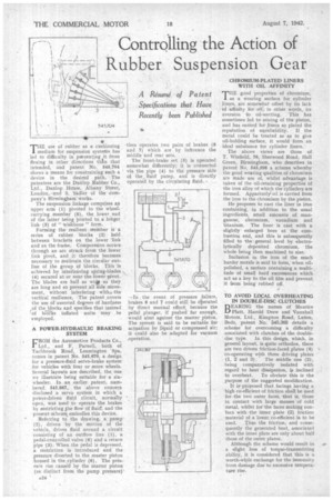
FROM the Automotive Products Co., Ltd., and F. Parnell, both of Taclibrook Road, Leamington 'Spa, comes in patent No. 545,670, a design for a pressure-fluid servo-brake system for vehicles with four or more wheels. Several layouts are described, the one we illustrate being suitable for a six
bered 545,667, the above concern disclosed a servo system in which a power-driven -fluid circuit, normally open, was used to operate the brakes by restricting the flow of fluid, and the present schemq embodies this device.
Referring to the drawing, a pomp (2), driven by the motion of the vehicle, drives fluid around a circuit consisting of an outflow line (1), a pedal-controlled valve (6) and a return pipe (3). When the pedal is depressed, a restriction is introduced and the pressure diverted to the master piston housed in the cylinder (6). The pres-• sure rise causid by the master piston (as dis,tinct from the pump pressure)
then operates two pairs of brakes (8 and 7) which are by inference the middle and rear sets.
The front-brake set (5) is operated somewhat differently; it is connected via the pipe (4) to the pressure side of the fluid pump, and is directly operated by the circulating fluid.
-In the event of pressure failure, brakes 8 and 7 could still be 4:Iterated by direct manual effort, because the pedal plunger, if pushed far enough, would abut against the master piston. The system is said to be suitable for actuation by liquid or compressed air; it could also be adapted for vacuum operation.
CHROMIUM-PLATED LINERS WITH OIL AFFINITY •
THEgood properties of chromium, as a wearing surface for cylinder liners, are somewhat offset by its lack of affinity for oil,. in other words, its aversion to oil-wetting. This has sometimes led to seizing of the piston, aud has earned for liners so plated the reputation of unreliability. If the metal could be treated so as to give oil-holding surface, it would form an ideal substance for cylinder liners.
The above views are those of
T. Winfield, 76, Sherwood Road, Hall Green, Birmingham, who describes in patent No, 545,598 a scheme whereby the good wearing qualities of chromium are made use of, whilst advantage is taken of the oil-retaining properties of the iron alloy of which the cylinders are formed. Apparently:oil is carried from the iron to the chromium by the piston. He proposes to cast the liner in iron containing, in addition to the usual ingredients, small amounts of manganese, chromium, vanadium and titanium. The liner is cast with a slightly enlarged bore at the combustion end, and this is subsequently filled to the general level by electrolytically deposited chromium, the whole being then machined to size. Inclusion in the iron of the much harder metals is said to form, when oilpolished, a surface containing a multi-• tucle of small hard excresences which act as a key to the oil film and prevent it fsom being rubbed off.
TO AVOID LOCAL OVERHEATING IN DOUBLE-DISC CLUTCHES BEARING the names of Maurice Matt, Harold Drew and Vauxhall Motors, Ltd., Kimpton Road, Luton, Beds, patent No. 545,365 details a scheme for overcoming a difficulty associated with clutches of the double
. disc type. In this design, which, in general layout, is quite orthodox, there are two driven friction-faced plates (4) co-operating with three driving plates
(1, 2 and 3). The middle one (2), being comparatively isolated with regard to heat dissipation, is inclined
to overheat. To obviate this is the purpose of the suggested modification. It is-proposed that facings having a
• high cosetficient of friction shall be used for the two outer faces, that is, those in contact With large masses of cold metal, whilst for the faces making contact with the inner plate (2) friction .material of a lower co-efficient is to be used. Thus the friction, and consequently the generated heat, associated with the inner plate are only about half those of the outer plates.
Although the scheme would result in a slight loss of torque-transmitting ability, it is considered that this is a worth-while exchange for the immunity from damage due to excessive temperature rise.