


A GERMAN SIX-WHEELER WITH CARDAN DRIVE.
Page 45
Page 46
If you've noticed an error in this article please click here to report it so we can fix it.
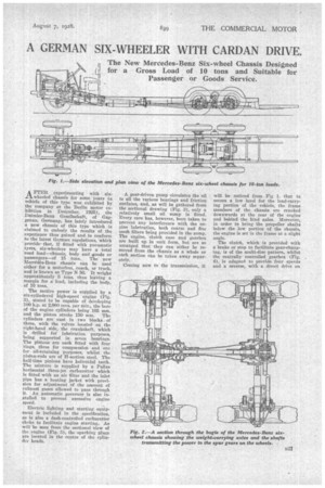
_n The New Mercedes-Benz Six-wheel Chassis Designed (1 for a Gross Load of 10 tons and Suitable for Passenger or Goods Service.
A FTER experimenting with six.t.l_wheeled chassis for some years (a vehicle of this type was exhibited by the company at the Berlin motor exhibition in December, 1925), the Daimler-Benz Gesellschaft, of Gaggenau, Germany, has lately introduced a new chassis of this type which is claimed to embody the results of the experience thus gained and to conform to the latest German regulations, which provide that, if fitted with pneumatic tyres, six-wheelers may have a total road load—chassis, body and ,goods or passengers—of 15 tons. The new 1■IereAdes-Benz chassis can be used either for a motorbus, coach, or truck, and is known as Type N 56. It weighs approximately 5 tons, thus leaving a margin for a load, including the body, of 10 tons.
The motive power is supplied by a six-cylindered high-speed engine (Fig. 3), stated to be capable of developing 100 h.p. at 2,000 revs, per min., the bore of the engine cylinders being 105 mm. and the piston stroke 150 mm. The cylinders are cast in two blocks of three, with the valves located on the right-hand side, the crankshaft, which is drilled for lubrication purposes, being supported in seven bearings. The pistons are each fitted with four rings, three for compression and one for oil-retaining purposes, whilst the piston-rods are of H-section steel. The half-time pinions have helicoidal teeth. The mixture is supplied by a Pallas horizontal three-jet carburetter which is fitted with an air filter and the inlet pipe has a heating jacket with provision for adjustment of the amount of exhaust gases allowed to pass through it. An automatic governor is also installed to prevent excessive engine speed.
Electric lighting and starting equipment is included in the specification, as is also a dash-controlled carburetter choke to facilitate engine starting. As will be seen from the sectional view of the engine (Fig. 3), the sparking plugs are located in the centre of the cylinder heads.
A gear-driven pump circulates the oil to all the various bearings and friction surfaces, and, as will be gathered from the sectional drawing (Fig. 8), only a relatively small oil sump is fitted. Every care has, however, been taken to prevent any interference with the engine lubrication, both coarse and fine mesh filters being provided in the sump. The engine, clutch case and gearbox are built up in unit form, but are so arranged that they can either be removed from the chassis as a whole or each section can be taken away separately.
Coming now to the transmission, it
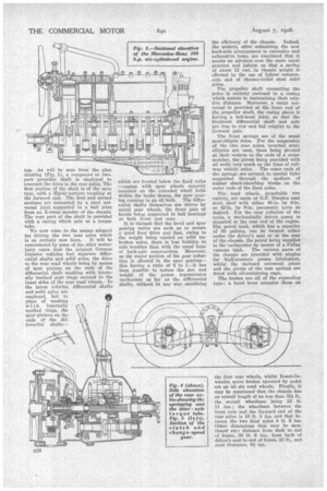
will be noticed from Fig 1. that to secure a low level for the load-carrying portion of the vehicle, the frame members of the chassis are cranked downwards at the rear of the engine and behind the hind axles. Moreover, in order to bring the propeller shafts below the low portion of the chassis, the engine is set in the frame at a slight angle. The clutch, which is provided with a brake or stop to facilitate gear-changing, is of the multi-disc pattern, whilst the centrally controlled gearbox (Fig. 4), is adapted to provide four speeds and a reverse, with a direct drive on top. As will be seen from the plan drawing (Fig. 1), a compound or twopart• propeller shaft is employed to transmit the drive to the rear axles. The first portion of the shaft is of the open type, with R Hardy-pattern coupling at the forward end. The first and second sections are connected by a steel universal joint supported in a ball joint from an X-cross member of the chassis. The rear part of the shaft is provided with a casing which acts as a torque tube.
We now come to the means adopted for driving the two rear axles which is on entirely new lines. It will be remembered by some of the older motorlorry users that the original German Daimler vehicles had separate differential, shafts and solid axles, the drive to the rear road wheels being bY means of spur pinions on the ends of the differential shaft meshing with internally toothed gear rings secured to the inner sides of the rear road wheels. In the latest vehicles, differential shafts and solid axles are employed, but in place of meshing with internally toothed rings, thi3 spur pinions on the ends of the diffovea tial shafts- which are located below the fixed axles —engage with spur wheels securely mounted on the extended wheel hubs within the brake drums, the spur gearing running in an oil bath. The differential shafts themselves are driven by spiral gear wheels, the front pair of bevels being supported in ball bearings at both front and rear.
It is claimed that the bevel and spur gearing ratios are such as to ensure a quiet final drive and that, owing to the weight being carried on solid unbroken axles, there is less liability to axle troubles than with the usual form of back-axle construction. Moreover, as the major portion of the gear reduction is effected in the spur gearing— this having a ratio of 8 to 1—it has been possible to reduce the size and weight of the power transmission mechanism as far as the differential shafts, without in any way sacrificing the efficiency' of the chassis. Indeed,
the makers, after submitting the new back-axle arrangement to extensive and exhaustive tests, are convinced that it marks an advance over the more usual practice and inform us that a saving of about 12 cwt. in chassis weight is effected by the use of lighter components and of chrome-nickel steel solid axles.
The propeller shaft connecting the axles is entirely enclosed in a casing which assists in maintaining their relative distance. Moreover, a metal universal is provided at the front end of the propeller shaft, the casing above it having a ball-head joint, so that the hindmost differential shaft and axle are free to rise and fall relative to the forward pair.
The front springs are of the usual semi-elliptic form. For the suspension of the two rear axles, inverted semielliptics are used, these being pivoted at their centres to the ends of a crossmember, the pivots being provided with oil wells very much on the lines of railway vehicle axles. The outer ends of the springs are secured to special links supported through the medium of rubber shock-absorbing blocks on the outer ends of the fixed axles.
The road wheels, detachable rim variety, are made of G.F. Simplex cast steel, shod with either 40-in. by 8-in. or 42-in. by 9-in, pneumatic tyres as desired. For the easy inflation of the tyres, a mechanically driven pump is mounted at the rear end of the engine. The petrol tank, which has a capacity of 33 gallons, can be located either under the driver's seat or at the rear of the chassis, the petrol being supplied to the carburetter by means of a Pallas vacuum tank. The various parts of the chassis are provided with nipples for high-pressure grease lubrication, whilst the enclosed universal joints and the pivots of the rear springs are fitted with oil-containing cups.
The brakes are all of the expanding typo; a hand lever actuates those on the four rear wheels, whilst Bosch-Dewandre servo brakes operated by pedal net on all six road wheels. Finally, it may be mentioned that the chassis has an overall length of no less than 35i ft., the overall wheelbase being 22 ft. 11 ins.; the wheelbase between the front axle and the forward end of the rear axles is 18 ft. 6 ins, and that between the two hind axles 4 ft. 5 ins. Other dimensions that may be mentioned are: distance from dash to end of frame, 30 ft. 6 ins., from back of driver's seat to end of frame, 23 ft., and road clearance, 9 ins.