


A Progressive Four wheel-steering Layout
Page 34
If you've noticed an error in this article please click here to report it so we can fix it.
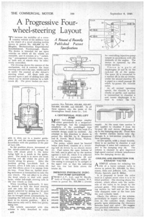
increase the mobility of a cross country vehicle vehicle of the military type is the object of a novel steering system shown in patent No. 523,656 by W. Blagden, Mechanization Experimental Establishment, Farnborough, Hants. The device is intended for use upon vehicles on which all the wheels are steerable, and it consists of a " switching " arrangement whereby front, rear, or both sets of wheels may be selectively controlled.
The drawing shows the essence of the mechanism; rod 8 controls the front steering and rod 2 the rear, whilst rod 9 is under the control of .the driver's steering wheel. All these rods are pivoted upon a pair of sliding bars (10) which can be moved endwise by a bellcrank (6). The pivot bushes are mov able in slots cut in a master guideplate (3), and the assembly operates in accordance with the position of the pair of bars (10).
In the position shown, movement of the driver-controlled rod swings the bars (10) about pivot 1, the latter being held in a notch in the guideplate. The result is to Move the front steering rod (8) whilst its pivot (5) travels along its groove. After the position giving two-thirds lock is reached, pivot 5 falls into a recess (4) and this allows pivot 1 to emerge from its trap. From then on, further steering movement is transmitted to only the rear wheels, The net effect is to allow the front wheels to deal with small locks, whilst full-angle steering calls in the rear wheels as well.
When travelling backwards, it may be desired to lock the front steering and use only the rear; this can he simply achieved by sliding bar 10 until pivot 5 is trapped in groove 7. This can be brought about automatically by coupling the bell-crank (6) to the gear lever in its reverse position. Rod 9 then moves only rod 2, their two pivots being free.
The vehicle associated with this scheme is fully described in other patents, Nos. t 23,654, 523,655, 523,657, 523,659, 523,660, and 523,967. In all these appears also the name of the Birmingham Small Arms Co., Ltd.
A CENTRIFUGAL FUEL-LIFT PUMP 0 S T fuel-raising pumps employ 1V1 either gearwheels or a reciprocating diaphragm, but the comparative simplicity of the centrifugal type should render it ideal for this work if a suitable design could be evolved. An attempt in this direction is shown in patent No. 523,703, by E. Beaumont and R. Dowle, Mead House, Waltonon-the-Hill, Surrey.
The pump, which must be located below tank-level, consists of a revolving 'bell (4) driven by an electric motor (1). Fuel enters the open bottom of the bell, and is piled up by the motion against a wall (2), where it is collected by a stationary scoop-tube (3) and delivered to the discharge outlet (5). The casing is arranged to be airtight at the upper end, so that the inflowing fuel can rise but little above the intake (6).
IMPROVED PNEUMATIC INJECTION-PUMP GOVERNOR CROM C.A.V., Ltd., and W. Nicolls, both of Warple Way, London, W.3, comes in patent No. 523,583 a scheme
for controlling injection-pump output in accordance with the demands of the engine. The device is operated by the intake suction. • There is a pair of diaphragms (3 and 5) on the rack-rod (2) of the pump. The space (4) is connected to a venturi (9) in the air intake, whilst the second chamber (7) is piped to a small passage (8) which by-passes the throttle valve, At all normal operating speeds, the throttle is open wholly_ or partly, and suction is transmitted to chamber 4 and causes diaphragm 3 to tend to reduce the fuel
supply. At the same time suction is also applied to chamber 7 from the by-pass (8) and moves diaphragm 6 up to the damping stop (6). From then on, further suction moves only diaphragm 3, a lost-motion coupling (1) then operating.
At low speeds, with a closed throttle, there is no suction in chamber 4 and diaphragm 5 takes full command, sub ject to the damping stop (6). The scheme is claimed to give improved high-speed control without interference from the damping device (6).
COOLING AND PROTECTION FOR EXHAUST VALVES
ASIMPLE scheme for reducing the risk of a burnt exhaust valve is shown in patent No. 523,693, by Rancomes, Sims and Jefferies, Ltd., Orwell Works, Ipswich, and N. Miller.
It is proposed to house the valve head in a special recess when it is in its lifted position. The drawing stews the scheme, which allows only the underside of the valve to be swept by the exhaust gases. This reduces the heating surface by half and at the same time dissipates some of the heat into the cool cylinder head.
Cltarly the efficacy of the scheme, particularly in respect of heat dissipation to the cylinder. head, . depends greatly upon minimizing the clearance between head and valve. We suggest that practical difficulties will be encountered in this connection.