


ANOTHER CHANGE-SPEED GEAR.
Page 32
If you've noticed an error in this article please click here to report it so we can fix it.
A Resume of Recently Published Patents.
A change-speed gear, the controlling principle of which is a friction drive, forms the subject of a specification thin Week by 3. W. Fisher, the number being 166,735. The actual transmission from engine to propeller. shaft is through. adifferential gear. The rotation of the differential cagvis controlled by means of a friction gear, which is also driven off the crankshaft. The arrangement is such that with the friction gear in what would normally be. neutral position„ the engine is driving. the propeller shaft directlyeon top• speed. As the driven disc moves out towards the euter edge of the driving disc and its speed of revolution increases, that of the propeller shaft decreases in relation to the speed of the crankshaft. Naturally, at a certain point, the: neutral gear is reached, when the friction gear is travelling at such a speed that, the propeller shaft is not revolving. Movement of the friction disc further away from the centre, increasing its speed-beyond that critical point, effects a reverse.
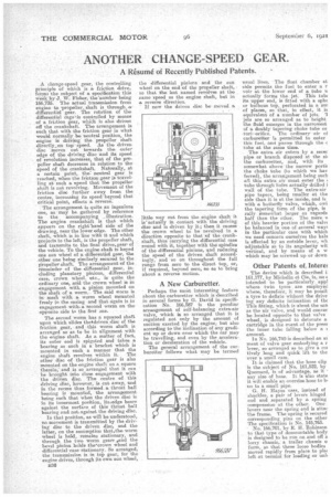
The arrangement is quite an ingenious one, as may be gathered by reference to the accompanying illustration. The engine crankshaft is that which appears on the right hand side of the drawing, near the lower edge. The other shaft, which is in line with it and which projects to the left, is the propeller shaft, and transmits to the final drive,,gear• of the vehicle. To the engine shaft is keyed one sun wheel of a differential gear, the other one being similarly secured to the Propeller shaft. The arrangement of the remainder of the differential gear, including planetary pinions, differential case, crown wheel, etc., is quite the ordinary one, and the crown wheel is in engagement with a pinion mounted on the shaft, of a worn. The said worm is in mesh with, a worm wheel mounted freely in the casing and that again is in engagement with.a second worm on the opposite side to the first one.
The second worm has a squared shaft upon which slides thetelriven disc of the friction gear, and this worm shaft is arranged so as to be in alignment with the engine shaft. As a matter of fact, its outer end is spigoted and takes a bearing as such in a. bracket which is mounted in such a manner that the
engine shaft revolves within it. The other disc of the friction gear is also mounted on the engine shaft on a square therein,' and is so arranged that it can be brought into close engagement with the driven disc. The centre of this (hiving disc, however, is cut away, and in the recess thus formed ,a thrust ball bearing is mounted, the arrangement being such that when the driven disc is in its innermost position, itstedge bears against the surface of this' thrust ball bearing and not against the driving disc.
In that position, as will be understood, no movement is transmitted by the driving disc to the driven disc, and the latter, on the assumption thatethe worm wheel is held, remains stationary, and through the two worm gears land the bevel pinion holds thecrown *heel and differential case stationary. -So arranged, the transmission is in top gear, for the engine drives, through its own sun wheel,
B36 the differential pinions and the sun wheel on the end of the propeller shaft, so that the feet named revolves at the same speed as the engine shaft, but in a reverse direction.
If now the driven disc be moved a
little way out from the engine shaft t is' actually in contact with the driving disc and is driven by it.; then it causes the crown wheel to be revolved in a direction opposite to that of the crankshaft, thus carrying the differential case round with it, together with the spindles of the differential pinion.s, and reducing the speed of the driven shaft accordingly, and so on throughout the full range from zero to the direct top, or, if required, beyond zero, so as to bring about a reverse motion.
A New Carburetter.
Perhaps the most interesting feature about the carburetter which is described in several forms by G. David in specification No. 166,587 is the peculiar arrangement of self-balancing extra-air valve, which is so arranged that it is regulated not only by the amount of suction exerted by the engine, but also according to the inclination of any gradient up or down over which the car may be travelling, and even by the acceleration or deceleration of the vehicle.
The general arrangement of the carburetter follows what may be termed -usual lines. The float chamber at side permits the fuel to enter a r voir at the lower end of a tube v, actually forms the jet. This tub( its upper end, is fitted with a sphe or bulbous top, perforated in a am of places, so that, in effect, it is equivalent of a number of jets. 'I Jets are so arranged as to height the fluid emerges in the narrowest of a doubly' tapering choke tube or turi. orifice, The ordinary air of carburetter is permitted to enter this fuel, and passes through the c tube at the same time.
The extra air enters by a secer pipe or branch disposed at the Eli the carburetter, and, with its somewhat above the narrow portic the choke tube (to which we hay ferred), the arrangement being such all thie extra air 'must enter the 1 tube through holes actually drilled i wall of the tube. The extra-air pipe tapers, being smaller at the side than it is at the inside, and is with a butterfly valve, which, owi the tapering form of the pipe, is rally .somewhat larger as regards half than the other. The mere of this heavier portion of the valv( be balanced in one of several ways in the particular case with which we need concern .ourselves the bale is effected by an outside lever, wh adjustable as to its angularity wit vertical, and by means of a w which may be screwed up or down
. Other Patents of, Intere: The device which is described i 161,177, by Michelin et Cie, leen° < intended to be particularly, app] where twin tyres are employed where, therefere, it may he poseik a tyre to deflate without the drive jug any definite intimation of the This fitting, which is -about the san as the air valve, and would conver be located opposite to that valve wheel, is designed to detonate a cartridge in the event of the press the inner tube falling below a ( amount,
In No. 166,740 is described an ax ment of valve gear embodying a r lever, so arranged .as to give a cot tively long and quick lift to the over a small cam.
It is claimed that the hose clip is the subject of No. 161,522, by Quemard, is of advantage, as it • any size of hose. It is also state it will enable an oversize hose to b. on to a small pipe. G.. H. Hayes uses, instead of *shackles, a pair of levers hinged end and separated by a spring -compression .at the other. One levers near the spring end is attac 'the frame. The spring is secured corresponding pins on the other The specification is No. 145,763.
No. 166,701, by K H. Robinson to that type of demountable body is designed to be run on and off A lorry chassis,a trailer chassis o form so that these loose bodies moved rapidly from place to pla( left at termini for loading or unh