


OVERHAULING THE VULCAN.
Page 26
Page 27
Page 28
Page 29
If you've noticed an error in this article please click here to report it so we can fix it.
No. 19.—The V.S.C. 30 cwt. and 2 ton Chassis—Simplicity and Accessibility thE Leading Features—Dismantling Before Overhaul—Dealing with the Units.
NO REPAIRER worthy of the name: need have any fear of dealing with the repairing or complete overhauling of the Vulcan vehicle. • It has been designed with a view to making every detail as simple as possible, and the parts are so arranged that they can be removed with rapidity and ease. As all the nuts and bolts are standard no special spanners are required, also no special appliances are necessary for withdrawing the various parts, and the repairer does notacquire to use anything except a standard set of mechanic's tools; this, of eourse apart from any machining which may have . to be done during an overhaul.
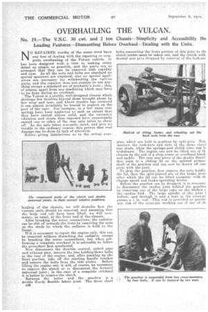
The Vulcan is a sturdy, well-designed chassis which develops few troubles beyond those brought about by fair wear and tear, and. where trouble has occurred it can almost invariably be traced to neglect on the part of the user. For instance, in a few cases rear springs have been neglected to such an extent that they have rusted almost solid, and the excessive vibration and strain thus imposed have occasionally caused one or other of the rear axle tubes to shear off. As the axle tubes are/quite stout, and give no trouble in the ordinary course, this proves that real damage can be done by lack of attention. Before giving instructions as to the actual over hauling of the. chassis, we will describe how the various, units. should be removed, and assuming that the body and cab have been lifted, we will commence, as usual, at the front end of the -chassis, After breaking the water connections, the radiator can be slid off towards the front by removing the nuts on the studs. by which the radiator is herd to the frame.
If it is necessary to repair the engine only, this can be removed without disturbing the radiator, except by breaking the :water connections, -but when performing a complete overhaul it is advisable to follow the procedure first mentioned. Now disconnect the throttle control, petrol pipe and exhaust pipe, remove the two holding-down belts at the rear of the engine, and, after packing up the front portion, take off the starting handle bracket and remove the bolts from the side plates. Before lifting the engine out, it will, of course, be necessary to remove the clutch or to disconnect the forward universal joint ; in the case of a complete overhaul it is better to remove the clutch.
. Between the latter and the gearbox is a double Hardy flexible fabric joint. The. three short c30
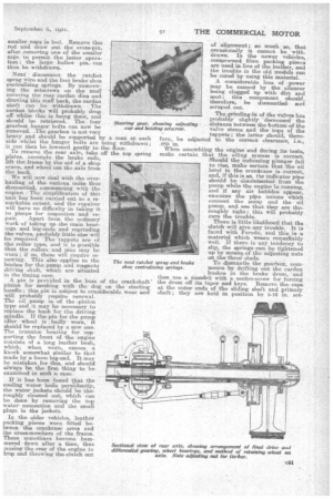
bolts connecting the front portion of this joint to tin clutch centre must be taken out, and the clutch with drawal arm pins dropped by removal of the fork-enC pins, which are held in position by split-pins. Nex unscrew the lock-nuts and nuts of the three elate] star studs, when the springtaand clutch cone can la withdrawn. The engine can now be lifted out of th chassis by the aid of a shop crane or overhead block and tackle. Therear star piece of the double flexibl disc joint is a sliding fit on the splined primar shaft of the gearbox and can now be drawn off eon plete with the joint. To drop the gearbox, first remove the nuts holdin the lid, then the. split-pinned pin of the brake level after which the lid can be lifted complete with th change speed and brake-operating levers. Before the gearbox can be dropped, it is necessar to disconnect the c.ardan joint behind the gearbom by removing one of the large caps on the bushes t the eardan fork. The large spindle of the joint i hollow, and through it and a hole in the cross-pi passes a in. rod. This rod is provided to preven any risk of the cross-pin working out if one of th smaller caps is lost. Remove this rod and draw out the cross-pin, after removing one of the smaller caps to permit the latter operation; the large hollow pin. can then be withdrawn.
Next disconnect the ratchet sprag wire and the foot brake shoe centrahzing springs. By unscrewing the setscrews on the muff covering the rear °exam dies and drawing this muff back, the earden shaft can be withdrawn. The eardan blocks will probably drop off whilst this is being done, and should be retrieved_ The four gearbox hanger bolts can now be removed. The gearbox is not very heavy and should be supported by a man at each side whilst the hanger bolts are being withdrawn; ii can then be lowered gently to the floor. Te remove the rear axle, take off the top spring plates, uncouple the brake rods, lift the frame by theaid of a shop crane, and wheel out the axle from the back.
We will now deal with the overhauling of the, various units thus dismantled, .commencing with the engine. The simplification of this unit has been carried out to a remarkable extent, and the repairer will have no difficulty in taking it to pieeps for inspection and re
pair. Apart from the ordinary work of taking up the main bearings and big-endsand regrinding the valves, probably littleelse will be required. The tappets are of the roller type, and it 3s possible that the rollers and pinS may be worn ; if so, these will require renewing. This also applies to the bushes for the pump and magneto driving shaft, which are situated in the timing ease.
A pin is provided in. the boss of the crankshaft pinion for meshing with the• dog on the starting hurdle.; this pin is subject to .considerable wear and will probably require renewal. The oil pump is of the ,pinion type and it may be necessary to replace the bush for the driving spindle. If the pin for the pump idler wheel is badly worn, it sbOuld be replaced by a new one. The trunnion bearing for supporting the front ofethe engine consists of a long leather bush, which, when worn, causes a knock somewhat similar to that made by a loose big-end. It may be mistaken for this, and should' always be the first thing to be examined in such a ease.
If it has been found that the cooling water boils persistently, the water jackets ,should be thoroughly cleaned out, which can be done by removing the top water connection and the small plugs in the jackets.
In the older vehicles, leather packing pieces were fitted between the crankcase arms and the cross-members of the frame. These sometimes become hammered down after a time, thus musing the rear of the engine. to imp and throwing the clutch out
of alignment; so much so, that occasionally it cannot be 'withdrawn, In the newer vehicles, eoneareeeed fibre packing pieces are used in lieu of the leather, and the trouble in the old models can be cured by using this material.
A considerable loss of •power may be caused by the silencer being clogged up with dirt and soot; this component should, therefore, be dismantled wed scraped out.
The,grinding-in of the valves has probably slightly 'decreased the distance between the bottom of the valve stems and the tops of the tappets; the latter should, thereadjusted to the correct clearance, i.e., When assembling the engine and during its tests, make certain, that the oiling system is correct. Should the indicating plunger fail to -title, make certain that the oil level in the crankcase is .correct, and, if this is so, the indicator pipe should be disconnected from the pump while the engine is running, and if any air bubbles appear, examine the pipe unions which connect the sump and the oil pump, and see that. they are thoroughly tight; this will probably cure the trouble.
There is little likelihood that the clutch will give. any trouble. It is faced with Ferodo, and this is a material which wears remarkably well. If there is any tendency to slip, the springs can be tightened up by means of the adjusting nuts on the three studs,
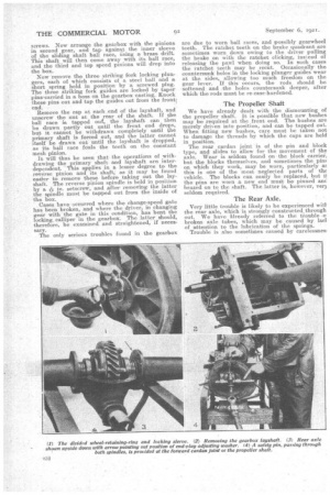
To dismantle the gearbox, commence by drifting out the cardan bushes in the brake drum, and then use a mandril with a centre-screw for forcing the drum off its taper and keys. Remove the cape at the outer ends a the sliding shaft and, primary shaft; they held in position by 5-16 in. set
are screws. Now arrange the gearbox with the pinions in second gear, and tap. against the inner sleeve of the sliding shaft ball race, using a brass drift. This shaft will then come away with its ball race, and the third and top speed pinions will drop into the box.
Now remove the three striking fork locking plungers, each of which consists of a steel ball and a short spring held in position by a screwed plug. The three striking fork guides are locked by taper :pinsocarried in. a boss on the gearbox :casting. Knock these pins out and tap the guides out from the front' end.
Remove the cap at each end of the layshaft, and unscrew the nut at the rear of the shaft. If the ball race is tapped out, the layshaft can then be drawn partly out until the front end drops, but it cannot be withdrawn completely until he primary shaft is forced out, and the latter cannot itself be drawn out until the layshaft is dropped, as its ball race fouls the teeth on the constant mesh pinion. . It will thus be seen that the operations of withdrawing the primary shaft and layshaft are interdependent This applies in alesser degree to, the reverse pinion and its shaft, as it may be found easier to remove these before taking out the layshaft. The reverse pinion spindle is held in Position by a A in. setscrew, and after removing the latter the spindle must be tapped out from the inside of the box.
Cases have occurred where the change-speed gate has been broken, and where the driver, in changing gear with the gate in this condition, has bent the locking, calliper in the gearbox. The latter should, therefore, be examined, and straightened, if necessary. The only serious troubles found in the gearbox are due to worn ball races, and possibly gearwheel teeth. The ratchet teeth on the brake quadrant are sometimes worn down owing to the driver pulling the brake on with the ratchet clicking, instead of releasing the pawl when doing so. In such cases the ratchet teeth may be recut. Occasionally the countersunk holes in the locking plunger guides wear at the sides, allowing too much freedom on the gear lever. If this occurs, the rods_ should be softened and the holes countersunk deeper, after which the rods must be re-case-hardened.
The Propeller Shaft
We have already dealt with the dismounting of the propeller shaft It is possible that new bushes may be required at the front end. The bushes are merely driven into position, and can be tapped out When fitting new bushes, care must be taken not to damage the threads by which the caps are held in position.
The rear cardan joint is of the pin and block type, and slides to allow for the movement of the axle. Wear is seldom found on the block carrier, but the blocks themselves, and sometimes the. pine on which they work, may be worn, particularly as this is one of the most neglected parts of tau vehicle. The blocks cau easily be replaced, but if the pins are worn a new end muet be pinned mc. brazed on to the shaft. The latter is, however, veil seldom required.
The Rear Axle.
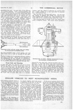
Very little trouble is likely to be experienced wit': the rear axle, which is strongly constructed through out. We have lready referred to the trouble o: broken axle tubes, which may be caused by ladl of attention to the lubrication of the springs, Trouble is also sometimes caused by carelessnes: 1,ssembling the axle. At each side of the differenis a thrust bearing. Now a thrust bearing will lc under a load of 6 lb. or a load infinitely greater a this, but if over-stressed theballst will press ) the case-hardened skin of the races, and the ring will very soon be ruined. Therefore, care old be taken to allow a, very slight amount of 7 by positioning suitable packing washers mem the axle sleeves and the central casing. is advisable, when dismantling the axle, careto note where packing washers are fitted. They old always be replaced at the same side.
he worm. gearing is self-centring, the easing, , being machined so that there is no necessity ;rouble with alignment. At the tear end of the in is a double thrust bearing, and this eari be tubed by screwing up or unscrewing the nut at end of the worm shaft. This nut is held,in posiL by a split pin, which it is most essential to ace after making adjustments. There -is an &lining felt washer at the front end of the worn2, this may have to be renewed.
ach rear wheel is held on in a very novel apd ative manner by a collar divided into halves held in a deep groove in the axle tube by a
-rangernent of fork and pin cardan joint and sliding die and pat joint on propeller shafts.
frig ring provided with a steel spring, one end thich turns into a here in one-half of the split Lr.
id play is taken up by phosphor-bronze washers ach side of the hub. These can be obtained in 2us thicknesses for the purpose of adjustment. re is an ail plug lie each hub cap, and-as much se as possible should be' injected through this.
Front Axle and Steering.
se stub axle pins are tapered and put in from bottom so that to remove them they must be ed out from the top. In the bottom of each axle is a. screwed adjusting bush in which is rdened steel disc, which acts as a thrust washer. .e is also a bush at the top of the stub axle. sometimes wears, and must then be renewed. he inner side of each stub axle is a leather washer, and the wheel is adjusted up against this by a collar sliding on a key and held in position by a, split-pinned nut.
The steering tie rod has ball joints. At one end the spring is against the inside cup, and at the other against the outside cup. The adjustment for each joint is by a screwed plug locked by a pin.
The steering gear is of the worm and wheel type with a complete wheel. The worm wheel spindle is tapered for the drop arm, and is provided with four keyways, so that the drop arm, and consequently the worm wheel, can be repositioned three times. End play on the worm is taken up by adjusting the bottom nut. This must first be released by unscrewing the locking nut and setscrew on the gear casing. These must, of course, be tightened up again when the adjustment has been effected. The only repair likely to be required in the steering gear is the renewal of the bushes. '