


THE ROADRAIL SYSTEM OF TRANSPORT,
Page 16
Page 17
If you've noticed an error in this article please click here to report it so we can fix it.
Preliminary Details of the Tractor Manufactured for Roadrails, Ltd., by Guy Motors, Ltd. What it Has Been Designed to Do. Vaporizing the Paraffin Fuel.
ERHAPS the Most renurkable.transport vehicle which has yet been introduced is now in
course of construction.. at the -works of Guy Motors, Ltd., Wolverhampton. This Vehicle is a tractor, which is being built for Rent-trails, Ltd., 1, Dover Street, St.. James's, London, S.W. for use in connection with the Stronach-Dutton Roadrail system of traction, which was first developed in S.W. Africa to meet .military requirements, but which presented such vast Potentialities that it is now being developed for civilian use, particularly in virgin country; where the cost of installing, the ordinary broad-gauge railway,system is prohibitive, and where even the east of the ordinary light railway is too great. The total expenditure for laying a Roadrail track is from £1,000 to £2,000 per mile, according to the difficulties with which the engineers have to contend, whilst the light, railway costs anything from 28,000 to £10,000 per mile. The system is designed entirely to -replace light railways, and even to be used as a substitute. for heavy guage railways, where the traffic is insufficient to justify the laying,_ of standard gauge line. The system was described briefly by us in our issue of June 21st, but it may be interesting to give a few details.
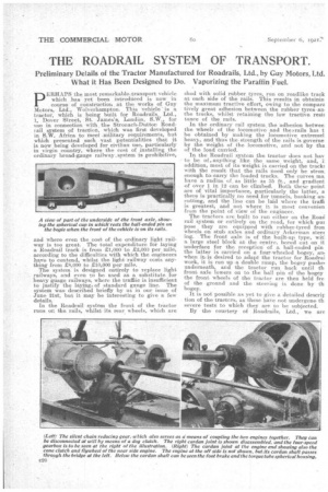
In the Roadrail system the front of the tractor runs on the rails, whilst its rear wheels, which are shod with solid rubber tyres, run on roadlike track at each side of the rails. This results in obtainin the maximum tractive effort, owing to the compare tively great adhesion between the rubber tyres an the tracks, whilst retaining the low tractive resiE tance of the rails.
In the ordinary rail system. the adhesion betwee the -wheels of the locomotive and the s.rails has t be obtained by making the locomotive extremel heavy, and thus the strength of the rails is governe by the weight of the locomotive, and not by the of the lead carried.
In the Roadrail system the. tractor does not hay to be of anything like the same weight, arid, i addition, most of its weight is carried on the trackF. Ivith the result that the rails need only be stroll; enough toL carry the loaded trucks. The curves ma, have a radius of as little as 35 ft., and gradient of over 1 in. 12 can be climbed. Both these point are of 'vital importance, particularly the latter, a there is practically no need for tunnels, banking an cutting, and the line can be laid where the trot& is greatest; and not where it is most convenien from the point of view of the engineer. The tractors are built to run either on the Road roll system or entirely on the road, for which pun pose they are equipped with rubber-tyred iron wheels on stub axles and ordinary Ackerman steer ing. . The front axle is of the built-up type, witl a large steel block at the centre, bored out on it underface for the . reception of a ball-ended pin the latter is carried on a four-wheeled bogey, an when it is desired to adapt. the tractor for Roadrai work, it is run up -a double ramp, the bogey pushel underneath, and the tractor run back until th front axle lowers on to the ball pin of the bogey the front wheels of the tractor are then held ire of the ground and -the steering is done by th bogey.
It is not possible as yet to give a detailed descrip tion of the traotors, as these have not undergone th, severe tests to which they are to be subjected. By the courtesy of Roadrails, Ltd., we are however, enabled to give a, general description, accompanied by several illustrations, of the various component parts.
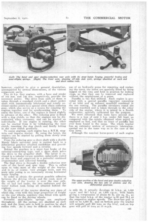
Two 25 h.p. Guy engines, with a bore and stroke of 102 mm. and 140 mm. respectively, provide the necessary power. The drive from each of these is taken through a standard clutch and a short eardan shaft with automatically lubricated and totally enclosed cardan joints to aspecial silent chain reducing gear, which also selves as a means for coupling the engines together and for synchronizing them. To assist the latter, one of th.e engines is timed slightly in advance of the other. The reducing gear is fitted with a dog clutch, so that the engines can be disconnected when necessary, and can be started up individually.if one engine is running, the other can be started from it by withdrawing the cone clutch, inserting the dog clutch and finally letting in the cane clutch gradually..
To assist starting, each engine has a B.T.11. magneto and impulse starter. By using the latter, the engines can be started by pulling them slowly over compression.
From the reducing gear a short shaft with a double Hardy fabric universal joint is carried back to a substantial gearbox situated ,amidships and providing four speeds forward and-a reverse. Behind the gearbox is a stout foot brake of the external-contracting type, and. a short shaft takes the drive to the propeller shaft. The latter is enclosed in a tubular torque member, spherically ended at the front and supported in a powerful combined cross-memberand spherical ho-using.
The final drive is through a doable reduction rear axle of the bevel and spur type. This is called upon to take most of the, weight of the tractor, and it is, of course, very strongly built, and the . main axle casing is an immensely strong horizontal banjo forging. In order to obtain the greatest possible adhesion between the driving wheels andthe road, most of the weight of the tractor is over the rear axle, the oil and fuel tanks, the two radiators and the water ballast tank being all situated behind the engines.
In the event of the tractor showing any signs of wheel slip, even with this large proportion of weight on the rear wheels, auxiliary rims fitted withspuds can be fixed to the driving wheelsk. Powerful semi-elliptic springs are employed throughout. All the springs are shackled at each end, and the front axle is held in position by short radius rods. As it may be difficult to obtain the use of an hydraulic press for reining and replacing the tyres, the latter are specially fitted by 'being lagged on the rims and held in position by locking rings, so that they can be removed and replaced without the employment„ of a press.
Paraffin is the fuel utilized. Each engine is provided with a special paraffin .vaporizer consisting of an inlet and an exhaust manifold combined in the one casting. The paraffin circulates round the -exhaust manifold and is taken through to the other side. of the engine-, where it is mixed in a Zenith carburetter, specially calibrated for the purpose. , We were informed that tests have proved that there is a loss of only 5 h.p. under full load, as compared with the, results 'obtained when petrol is employed as fuel, and that no trace of paraffin has ever been found in the sump. The whole tractor has. an extensive system of automatic lubrication, carried out in the same way as in the case of the Guy. lorry.
Although the nominal horse-power of each engine
is only 25, it actually develops 30 b.h.p. at 1,000 r.p.m. and 39.7 b.h.p, at 1,000 r.p.m., with heads giving a compression Of about 65 lb. per sq. in., so that the total b.h.p. of the tractor is 60 and 79.4 at the respective engine speeds. The draw-bar pull is said to be 4,500 lb., and on bottom gear the tractor will actually pull 250 tans on the leve1. and,:on top gear will pull 50 tons at-13 m.p.h.