


PATENTS SUMMARIZED.
Page 24
If you've noticed an error in this article please click here to report it so we can fix it.
A C.A.V. Electric Starter.
C. A. Vandervell and Co., and A. E. Midgley, describe in specification N. 108,114 an improved construction of the driving gear of an electric self-starter for automobile engines. The improvement is mainly in connection with the manner of engagement of the starter With the gearing on the fqnvheel, and is supplementary to a:previous invention by the same patentees which as made public in specification No. 24,293 of 1914, The gear is of the type in which the driving pinion, on the 'shaft of the motor, STRIes endwise into mesh with the cogs on the rim of the engine flywheel. Movement of the pinion is effected hy.a preliminary longitudinal,motion of the armature shaft, under the .influe»ce of magnetic attraction. This is suppleMented by. movement of the pinion cc its shaft caused by the preliminary revolation, within it, of the screwthreaded shaft. The inertia; of the pinion operates to prevent it from immediately revolving in concert with the shaft. The Principal aim of the C.A.V. invention, as now disclosed, is the reduction of the longitndinahmoventent of the 'armature 'shaft to a minimum.
The method employed is to use a friction disc for the first engagement between the starting motor and flywheel. The engagement of this disc is effected by the movement of the armature shaft of the motor, acting under the influence
of magnetic, attrattion. The distance moved is small and is all the endwise Motion which the shaft is called Kinn to make. The driving pinion of the starter gear revolves le unison with the friction disc, but can move longitudinally with respect to that disc. The gear is mounted, as ia enstomary in other starters of this or a similar type,. on a screwed shaft, which is driven by the motor. The friction disc' on engagement with the flywheel of the -engine, naturally tends to fall behind the motor shaft in speed, and in consequence aids materially the inertia effect of the pinion, and causesit to move along the screwed shaft into its operative position with greater facility.
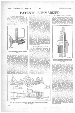
A Sparking Plug Improvement.
In the introductory paragraph to patent specification No. 107,888, K. E. Lee Guiness, of Aranmore, Kingston lEll, draws attention to the fact that'in many sparking plugs the insulation is not so efficiently arranged as it might be. It is in those cases practically Uniform in thickness along the whole length of the electrode, except at the extreme tip. He proceeds then to describe, his . patented construction in which this failing is overcome. As may be seen by reference to our illustration, near the exposed end of the electrode, where a wall of air of considerable thickness is interposgd between the electrode and the casing of the plug, the mica wrapping is thinned down. Where, however, the mica is the only insulation which intervenes between electrode and case, the wrapping is made thicker. There are also several minor details of the construction of this plug, to which reference is made in the specification. Maskell Self-contained Agrimotor.
J. W. Maskell's self-contained motorplough is known to not a few of our readers. It is of the type in which the whole weight of the machine is carried single central driving wheel. The imp:ement bar is supported, as nearly as possible, in the same 'plane as the axle Efficient distribution of the insulation is the chief claim made for this sparking plug.
of this driving wheel. In order to afford lateral stability, a small* land wheel is provided, being carried by a framework which juts out from that side of the machine which is farthest from the furrow. This agrimotor was first described in patent No. 13,150 of 1915.
In practice, it has been found that the small wheel had the undesired effect of investing the machine with a constant tendency to turn to the side on which it was situated. The object of the present invention, which is fully deficribed in specification No. 107,941; is to overcome this difficulty. It has been attained by the provision of a guide-wheel whieh runs in the newly-cut furrow. At the front of the machine, carried by two suitably-disposed bearings, is a transverse shaft. Secured to this shaft is an arm about two feet long, at the outer end of which is attached a small wheel.' The disposal of the parts is such that this wheel runs in the furrow which was ploughed on the previous traverse of the field, 'and, by pressing against the 'side of the furro—W, it oeposes the tendency of the motor to turn in the oppoFite direction. Attaching the arm to a shaft as described allows the wheel to rise and fall in harmony with inequalities in the ground surface, and by fastening a lever to the outer end of the shaft, and coupling the lever to another within easy reach of the driver, he can thus lift the front wheel out of the furrow whenever it is desired to turn the implement round.