 1
1 2
2 3
3 4
4 5
5 6
6 7
7 8
8 9
9 10
10 11
11 12
12 13
13 14
14 15
15 16
16 17
17 18
18 19
19 20
20 21
21 22
22 23
23 24
24 25
25 26
26 27
27 28
28 29
29 30
30 31
31 32
32 33
33 34
34 35
35 36
36 37
37 38
38 39
39 40
40 41
41 42
42 43
43 44
44 45
45 46
46 47
47 48
48 49
49 50
50 51
51 52
52 53
53 54
54 55
55 56
56 57
57 58
58 59
59 60
60 61
61 62
62 63
63 64
64 65
65 66
66 67
67 68
68 69
69 70
70 71
71 72
72 73
73 74
74 75
75 76
76 77
77 78
78 79
79 80
80 81
81 82
82 83
83 84
84 85
85 86
86 87
87 88
88 89
89 90
90 91
91 92
92 93
93 94
94 95
95 96
96 97
97 98
98 99
99 100
100 101
101 102
102 103
103 104
104 105
105 106
106 107
107 108
108 109
109 110
110 111
111 112
112 113
113 114
114 115
115 116
116 117
117 118
118 119
119 120
120 121
121 122
122 123
123 124
124 125
125 126
126 127
127 128
128 129
129 130
130 131
131 132
132 133
133 134
134 135
135 136
136 137
137 138
138 139
139 140
140 141
141 142
142 143
143 144
144 145
145 146
146 147
147 148
148 149
149 150
150 151
151 152
152 153
153 154
154 155
155 156
156 Absorbed Braking Force Aids Acceleration
Page 85
Page 86
If you've noticed an error in this article please click here to report it so we can fix it.
Robert Clerk's Latest Gyreacta System being Tested
THE energy wasted by frequent braking when a passenger vehicle is engaged on stage-carriage work in a congested area may account for over 30 per cent. of the total fuel consumption. Any means of storing this energy that
enables it to be used to augment the motive power of the engine for subsequent acceleration of the vehicle offers, therefore, a worth-while gain in overall running economy. A device known as the Gyreacta, evolved by the British inventor Robert Clerk, gives this advantage and has a number of additional merits that can be exploited by the operator.
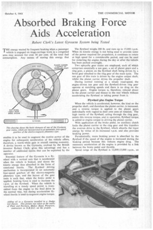
Essential feature of the Gyreacta is a flywheel with a vertical axis that is accelerated when the vehicle is braked. and stores the kinetic energy thus absorbed in the form of rotational inertia. The flywheel driving mechanism is incorporated in an automatic four-speed gearbox of the electro-magnetic planetary type, and the layout of the gear train is such that, when the brake pedal is applied, braking force is used to increase the r.p.m. of the flywheel When the vehicle is travelling at a steady speed power is transmitted from the engine to the final drive in the normal way, but during acceleration flywheel inertia is used to augment engine torque. The flywheel weighs 290 lb. and runs up to 15,000 r.p.m. When its kinetic energy is not being used to provide some of the power required for propulsion, it continues to rotate at high speed for a considerable period, and can be used for restarting the engine during the day or after the vehicle has been parked overnight.
Two epicyclic gear trains are employed, each of which comprises essentially a sun gear, a set of planet gears and a ring gear, a pinion on the flywheel shaft being driven by a bevel gear attached to the ring gear of the main train. The sun gear of this train is driven by the engine output shaft, whilst the planet carrier drives the propeller shaft.
During normal running' at a steady road-speed, the engine-driven sun gear and the flywheel-driven ring gear operate at matching speeds and there is no drag on the planet gears. Engine torque is, therefore, relayed direct to the planet carrier and thence to the rear wheels without accelerating the flywheel or taking power from it.
Flywheel plus Engine Torque
When the vehicle is accelerated, however, the load on the propeller shaft, and therefore the planet carrier, is increased, and a reverse torque is applied to the planet gears individually with regard to their own axes of rotation. The high inertia of the flywheel, acting through the ring gear, resists this reverse torque, and in operation, flywheel torque is added to engine torque in driving the planet carrier.
With application of the brake pedal, an auxiliary clutch locks the planet carrier to the ring gear and this transfers the overrun drive to the flywheel, which absorbs the input energy by virtue of its increased r.p.m. and also provides braking power.
Paradoxically, more braking power is absorbed by the flywheel if the speed of the engine is increased during the braking period because this reduces engine drag. The necessary acceleration of the engine is provided by a link between the brake pedal and throttle.
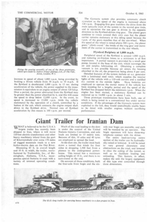
Speed range of the flywheel is 12,000-15,000 r.p.m., an increase in speed of about 1,000 r.p.m. being provided by braking a 10-ton vehicle from 30 m.p.h. to 10 m.p.h. If the flywheel is decelerated 1,000 r.p.m_ in 15 sec. during acceleration of the vehicle, the power supplied to the transmission is equivalent to an engine output of about 120 b.h.p. Over a period, the power abstracted from the flywheel may be greater than the power absorbed by it, and this will cause the speed to drop below 12,000 r.p.m. In the event, its speed is increased to 15,000 r.p.m. (with the vehicle stationary) by the operation of a clutch, controlled by a button in the cab, which connects the engine output shaft direct to the flywheel drive. Normal rate of flywheel acceleration by this means is 100 r.p.m per second. The Gyreacta system also provides automatic clutch operation as the speed of the engine is increased above 5J0 r.p.m. Engaging first gear transfers the drive from the main epicyclic train of the system to the second gear train, and in operation the sun gear is driven in the opposite direction to the flywheel-driven ring gear, The planet gears continue to rotate around their own axes but the planet carrier remains stationary at this idling speed because the r.p.m. of the gears matches that of the sun-wheel. When the speed of the wheel is raised above 500 r.p.m., the planet gears climb round " the inside of the ring gear and movement of the carrier is transmitted to the rear wheels.
Flywheel Periphery at 1,000 m.p.h.
Peripheral speed of the flywheel is around 1,000 m.p.h. and reducing air-friction losses to a minimum is of first importance. A partial vacuum is provided by a small gear pump, located in the base of the unit, which scavenges the air and surplus lubricating oil. Obtaining a complete vacuum is not possible because air enters the housing absorbed in the oil, the proportion being about 8 per cent.
Detailed features of the system include an a.c. generator with a laminated steel rotor, which supplies the interior lights of the vehicle with a 110-volt current and a rectified d.c. current to the outside lights. Slave batteries are employed to operate the starter motor if the vehicle has been standing for a lengthy period and the speed of the flywheel has dropped below the minimum r.p.m. When the engine has been started, a stationary flywheel can be motored up to 14,000 r.p.m. in about 3 min.
Three prototype transmissions have been built, one of which is being tested in a conventional bus under service conditions. If the advantages of the Gyreacta system were exploited to the full, they would undoubtedly enable buses to be fitted with smaller engines without sacrificing performance.