


Hydraulic System Applied to Clutch Operation
Page 36
If you've noticed an error in this article please click here to report it so we can fix it.
rROM the Rover Co., Ltd., and P. A.
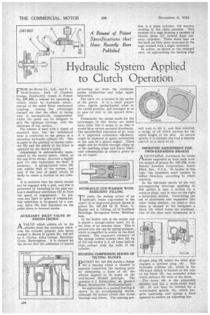
Scott-Iversen, both of Chesford Grange, Kenilworth, comes, in Patent No. 547,465, a scheme for operating a vehicle clutch by hydraulic mean, instead of the usual direct mechanical coupling. Among the advantages claimed are that the effect of facing wear is automatically compensated, whilst the pedal can be designed to give the optimum leverage, with the minimum of lost motion.
The scheme is used with a clutch of standard type, but the withdrawal lever is connected to the piston of a secondary hydraulic cylinder (4). This is piped to the primary or master cylinder (2) and the piston of the latter is operated by the driver's pedal.
Adjustment is automatically maintained by the master piston, which, at the end of its stroke, uncovers a supply port (1) that replenishes the fluid, if necessary. A spring-loaded valve (6) also admits fluid to the system, but only if the rate of pedal return be likely to create a vacuum in the cylinder.
It is desirable that the clutch should not be engaged with a jerk, and this is prevented by including in the pipe system a small-bore restriction (5) to limit the speed of engagement. To prevent any limit to speed of withdrawal, this restriction is by-passed by a oneway valve (3) that functions on the pedal down or forward stroke.
AUXILIARY INLET VALVE IN PISTON CROWN
AVALVE which admits air to the cylinder from the crankcase whenever the cylinder pressure falls below normal is shown in patent No. 547,317 by S. Clovves, Atlas Garage, Bordesley Green, Birmingham. It is claimed for the device that the admission of heated
oil-bearing air from the crankcase assists combustion and helps upper lubrication.
The valve (1) is located in the crown of the piston. It is a small poppet valve, lightly spring-loaded when in the closed position, and arranged so as to pass air only in the upward direction.
Presumably the claims made for the advantages of this device are based upon tests, but it seems to us that it would have certain material drawbacks. The uncontrolled admission of air, even if it improved volumetric efficiency, might be expected to upset carburation in the case of a petrol engine. 'There might also be trouble through oiling up of the sparking plugs and heavy lubricant consumption in either a petrol or an oil engine.
HYDRAULIC CUP-WASHER WITH RESILIENT FILLING
TO assist the sealing action of an hydraulic brake cup-washer is the object of an improved pattern shown in patent No. 547,258 by H. Pratt, G. Manley and A. Girling, all of Guildhall Buildings, Navigation Street, Birmingham.
In the hollow side of the rubber cup is placed a sponge-rubber insert (1) in „the form of an annular mass. This is pressed into the cup by spring pressure, which is amplified in action by the fluid pressure. The expansive tendency of the sponge rubber ensures that the lip of the cup-washer is at all times held in close contact with the walls of the cylinder.
BEARING COMPRISING SERIES OF TILTING BLOCKS
PATENT No. 547.306 details a design for a bearing which is claimed to separate completely the running parts by interposing a layer of oil; the scheme appears to be based on the well-known Michell principle. The patentee is J. Edmundson, 40, Queen's Road, Monkseatdn, Northumberland.
An application to a journal bearing is shown in an accompanying sketch, although the patent covers also thrust bearings and others. The running por tion is a plain cylinder, the novelty residing in the outer member. This consists of a cage housing a number of tiltable shoes (I) formed from cutaway cylinders. These shoes bear on the shaft on their inner faces and fit the cage recessa with a slight clearance.
In action, as shown in the enlarged view, oil approaching the leading edge will tend to lift it, and thus establish a wedge of oil which persists for the whole length of the shoe. At certain speeds, it is claimed, the load is entirely carried on a layer of oil.
IMPROVED ADJUSTMENT FOR TWIN-EXPANDER BRAKES
ADJUSTABLE abutments for brake shoes expanded at both ends form the subject of patent No. 547,226, from Bendix Aviation Corporation, South Bend, Ind., U.S.A. In brakes of this type, the abutment must operate in either direction, according to wheel rotation.
In the left-hand sketch of the two accompanying drawings applying to this patent is seen a section on a vertical plane, and in that on the right a horizontal section. Considering one set of abutments and expanders (the other being similar), we observe that there is secured to the backplate a block (5) which forms the abutment. One of the shoe ends terminates in a flanged plug (6) whilst the other shoe engages a screwed plug (4). The hydraulic cylinder (1), which in the left-hand sketch is located at the rear of the block (5), has extended yokes which embrace the webs of the shoes.
The screw (4) is the adjustable member and has a worm-wheel head (2). It can thus he rotated by a worm-ended spindle (3), which projects externally and carries a head squared to receive an adjusting key.