


An Ingenious New Engine
Page 74
If you've noticed an error in this article please click here to report it so we can fix it.
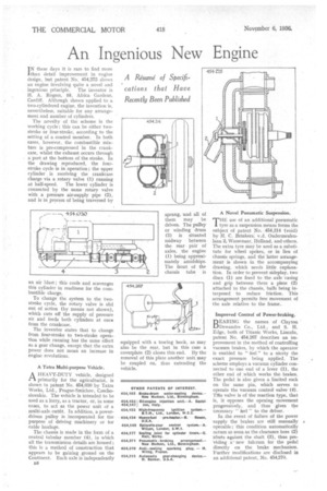
I N these days it is rare to find more than detail improvement in engine design, but patent No. 454,275 shows an engine involving quite a novel and
ingenious principle. The inventor is H. A. Rogers, 58, Africa Gardens, Cardiff. Although shown applied to a two-cylindered engine, the invention is, nevertheless, suitable for any arrangement and number of cylinders.
The novelty of the scheme is the working cycle ; this can be either twostroke or four-stroke, according to the setting of a control member. In both cases, however, the combustible mixture is pre-compressed in the crankcase, whilst the exhaust occurs through a port at the bottom of the stroke. In the drawing reproduced, the fourstroke cycle is in operation ; the upper cylinder is receiving the crankcase charge via a rotary valve (1) running at half-speed. The lower cylinder is connected by the same rotary valve with a pressure air-supply pipe (2), and is in process of being traversed by an air blast ; this cools and scavenges this cylinder in readiness for the combustible charge.
To change the system to the twostroke cycle, the rotary valve is slid out of action (by means not shown), which cuts off the supply of pressure air and feeds both cylinders at once from the crankcase.
The inventor states that to change from four-stroke to two-stroke operation while running has the same effect as a gear change, except that the extra power does not mean an increase in engine revolutions.
A Tatra Multi-purpose Vehicle.
A HEAVY-DUTY vehicle, designed primarily for the agriculturist, is shown in patent No, 454,030 by Tatra Works, Ltd., Prague-Smichov, Czechoslovakia. The vehicle is intended to be used as a lorry, as a tractor, or, in some cases, to act as the power unit of a multi-axle outfit. In addition, a powerdriven pulley is incorporated for the purpose of driving machinery or for cable haulage.
The chassis is made in the form of a central tubular member (4), in which all the transmission details are housed ; this is a method of construction that appears to be gaining ground on the Continent. Each axle is independently B8 sprung, and all of them may be driven. The pulley or winding drum (3) is situated midway between the rear pair of axles, the engine (1) being approximately amidships. The front of the chassis tube is equipped with a towing hook, as may also be the rear, but in this case a coverplate (2) closes this end. By the removal of this plate another unit may be coupled on, thus extending the vehicle. A Novel Pneumatic Suspension.
THE use of an additional pneumatic tyre as a suspension means forms the subject of patent No. 454,314 (void) by H. C. Brinkers; v.d. Oudermealenlaan 2, Wassenaar, Holland, and-others. The extra tyre may. be used as a substitute for wheel spokes, or in lieu of chassis springs, and the latter arrangement is shown in the accompanying drawing, which needs little explanation. In order to prevent sideplay, two discs (1) are fixed to the axle casing and grip between them a plate (2) attached to the chassis, balls being interposed to reduce friction. This arrangement permits free movement of the axle relative to the frame.
Improved Control of Power-braking.
BEARING the names of Clayton Dewandre Co., Ltd., and S. H. Edge, both of Titanic Works, Lincoln, patent No. 454,267 describes an improvement in the method of controlling vacuum brakes, by which the operator is enabled to " feel " to a nicety the exact pressure being applied. The scheme employs a vacuum cylinder connected to one end of a lever (1), the other end of which works the brakes. The pedal is also given a limited rock on the same pin, which serves to operate the vacuum control valve (4). Tills valve is of the reaction type, that is, it opposes the opening movement progressively, and thus gives the necessary " feel " to the driver.
In the event of failure of the power supply the brakes are still manually operable ; this condition automatically occurs so soon as the clearance bore (2) abuts against the shaft (3), thus providing a' new fulcrum for the pedal directly on the brake mechanism. I-?urther modifications are disclosed in an additional patent. No. 454,270.