


THE ENGAGEMENT OF STARTER PINIONS.
Page 30
If you've noticed an error in this article please click here to report it so we can fix it.
A Resume of Recently Published PatentSpecifications.
TN specification No. 279,895 the name of the Delco-Remy ■
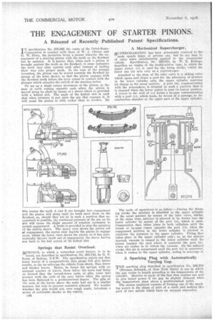
Corporation. is coupled with those of W. A. Chryse and G. W. Elsey, the invention being a means whereby the engagement of a starting pinion with the teeth on the flywheel can be assisted. It is known that, when such a pinion is brought against the teeth on the flywheel, in some instances the teeth may abut against each other instead of finding their way into proper mesh. In the case of the present invention, the pinion can be moved towards the flywheel by means of the lever shown so that the pinion engages with the flywheel teeth before the lever comes in contact with the plunger which actuates the switch of the starting motor.
To set up a slight rotary movement of the pinion, in the ease of teeth coming opposite each other, the pinion is moved along its shaft by means of a sleeve which is provided with a helical slot. The angle of the helical slot is such that when pressure is put upon the pin that engages it, it will cause the pinion to slide rather than to revolve. By this means the teeth A and Il are brought into engagement and the pinion slid along until its teeth meet those on the flywheel, so, should they not be in such a position that engagement is possible, the continued pressure of the pin on its slot will cause the slight amount of rotation necessary to permit engagement. A brake is provided to stop the spinning • of the sliding sleeve. The ripper view shows the pinion out of engagement, the centre view depicts the pinion in engagement, whilst the lower view shows the pinion as it has automatically thrown itself out of engagement, the sleeve having run back to the full extent of its helical slot.
Springs that Resist Overload.
SPRINGS, in which a somewhat novel feature is to be found, are described in specification No. 293,742,.by G. P. Innis, of Sydney, N.S.W. The specification points out that many leaves of a comparatively thin gauge will give better results so far as relieving the vehicle from shock, than fewer and thicker leaves. Hence, he forms his springs with an unusual number of leaves, those below the main leaf being so formed that the turned-down ends, or gibs, come into contact with the ends of the next leaves when the spring has been flattened to a predetermined degree. The gibs on the ends of the leaves above the main leaf act in a similar manner, but only to prevent excessive rebound. We wonder whether the gibs would not, over rough roads, introduce a series of noticeable shocks to the vehicle.
A Mechanical Supercharger.
SUPERCHARGING has been principally confined to the more speedy types of private ear, but its use may be of value when satisfaCtorily applied to the commercial vehicle. Specification No. 297,073, by W. R. Ridings, describes an engine of the double-piston type, in which the upper piston (A) is used for the firing stroke, whilst the lower one (a) acts only as a supercharger.
Attached to the stem of the inlet valve is a sliding valve which opens and closes a port for the admission of mixture to the lower cylinder only, the upper cylinder receiving its charge in the usual manner. A port (a), communicating with the atmosphere, is situated in such a position that it is exposed when the lower piston is near its lowest position. A •recess in the wall of (A) forms a by-pass communicating with a port (c), which leads, by means of a passage,. to the combustion chamber at the upper part of the upper cylinder.
The cycle of operations is as follow :—During the charging stroke the mixture is admitted to the upper cylinder in the usual manner by means of the inlet valve, whilst, at the same time, mixture is allowed to be drawn into the lower cylinder by means of the port (n), which is open. Compression then takes place in both cylinders until the recess or by-pass comes opposite the port (c), when the compressed mixture in the lower cylinder is allowed tu reinforce the pressure in the upper cylinder. Firing then takes place in the upper cylinder only ; . so, as the pistons descend, vacuum is caused in the lower cylinder until the piston reaches the spot where it uncovers the port (a), when air rushes in to reduce the vacuum. On the exhaust. stroke this air is compressed until the port (c) is uncovered, when it rushes to the upper cylinder, acting to scavenge it.
A Sparking Plug with Automatically Varying "Gap.
THE sparking plug described in specification No. 289,758 (Herman Schlaich, of New York State) is one in which the gap variesin length according to the temperature of the cylinder. Mention is made of the fact that engines are said to give better power if the gap be slightly widened when the temperature rises above a predetermined point.
The means employed consists of forming one of the sparking points in the shape of part of a circle and making this part of two metals which have an unequal expansion.