


USEFUL TRANSMISSION TIPS.
Page 31
If you've noticed an error in this article please click here to report it so we can fix it.
Interesting Contributions From Our Driver and Mechanic Readers.
ASKETCH of an interesting tool, by the aid of which the removal of a. heavy vehicle chain is greatly facilitated, is sent to us by "J.J.," of Keighley. • The sketch itself is almost self -explanatory. There is a double ratchet lever in the centre, operating on right or left-handed screws, upon which are mounted two nuts, with which are integral short levers or fingers, which
are turned over at the end se that they can conveniently be made to engage the rollers of the chain. The mode of operation is quite simple. The radius rod must. first be manipulated so as to slacken the chain as much as is necessary. The fingers of the tool should be, as a preliminary, separated to a sufficient distance to enable them to engage a pair of links, one at each side of the chain link. The ratchet lever is fhen operated to bring the fingers Closer together so as to tighten the chain sufficiently to take the load off the "joint bolt. The last. named can then be removed quite easily, when the operation of the ratchet lever must be reversed and the chain slackened so that the fingers may he removed from it.
" II.A.B.," of Rotherham, evidently thinks he has written to ns now so frequently that it is unnecessary for him to put his address at the head of his letter. His present communication, like that from " J.J.," also concerns chains, and, after reminding us that if they are to give good service roller chains Must be kept clean, he refers to the accompanying sketch of a tooli for effecting the cleaning operation.
It consists of a pair of brushes fastened together by two pieces of steel bar bent at right angles, the dimensions being such that when one of the two brushes makes contact with the side. of the chain the other will be brushing the rollers.
In use, the brush should be used first to take the dirt off. Itisshould then be soaked in paraffin and each roller cleaned in turn after which engine oil should be poured on to each link, holding a can below to catch any which may drip, as this can be used again.-ss
" In some places," he continues;-" I havb seen it recommended that graphite grease should be used for the lubrication of chains, but, unless a chain guard is fitted, this, to my mind, is not good practice, as the grease tends to pick up and retain duet and dirt.
" When fitting a new chain on an old vehicle it is advisable to see that the driving sprocket is not so much worn that. the teeth are hooked, as; in that case, the chain will not run well, and will be liable to mount the wheel. It is much more important than some drivers think that the chain should be at the correct tension, and a good way of testing this is to lift one-half of the chain whilst the wagon is stationary. A movement of 4 ins, should be pisssible."
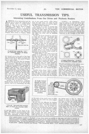
Another letter, from " J.G.," of Kilmarnock, is also about chain transmission. He had to remove worn sprockets from an Albion chassis, and, on atte pting the job, discovered that the thr ds at the ends of the shafts were so badly bruised that he could not even engage the extractor, Ho got over his difficulty by chaaing the threads while the shafts were still in place on the lorry. For this purpose he mounted a chasing tool on a box,j a-s
ii shown in the accompanying sketch, ing a small piece of square-section timber as a heel, just in the same way as tine uses. a T-rest in the lathe. He go it man to turn the road -wheel of the wagon (which was, of course, jacked tip) while the thread was being chased.
" A.W.K.," of Canterbury, found that the splines oa the end of his propeller shaft and in the boss of the union joint with which it coupled were so worn that it seemed as if a new shaft and coupling would be required. However, he set to work to effect a repair which, it seems to us, may only he temporary, as it necessitates a considerable reduction in the strength of the shaft.
We give particulars of his method, however, as it is Certainly interesting.
He commenced by boring out the boss of the coupling, as shown in Fig. 1, taking out all the splines so that the bore was perfectly smooth. He then took a square mandril, the diagonal of the square being equal to the bore of the coupling, and on it mounted four pieces of flat steel plate, as shown by the dotted lines in Fig. 2. These he turned, as shown in the same figure in full lines, so that the outside diameter was the same as the newly thored hole in the coupling. The result was that he had four pieces of metal, which, when fitted inside the boss of the coupling, would reduce the hole in it to a plain square. These pieces were secured in place by countersunk screws, which were subsequently riveted over; as shown in Fig. 3. The end of the shaft was then squared up to be a sliding fit in this hole, and the job was.completecl.