


HINTS ON MAINTENANCE.
Page 30
If you've noticed an error in this article please click here to report it so we can fix it.
How to Get the Best Out of a Vehicle, to Secure Reliability and to Avoid Trouble.
445. Improving the Oil Distribution System of the J-type Thornycroft Engine.
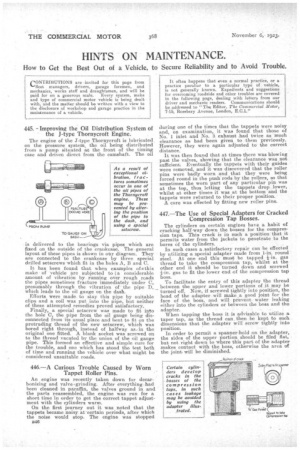
The engine of the 3'-type Thornycroft is lubricated. on the pressure system, the oil being distributed from a pump situated at the front of the timing case and driven direct from the camshaft. The oil is delivered to the bearings via pipes which are fixed on the outside of the crankcase. The •general layout of these pipes is shown in oh/. diagram. They are connected to the crankcase by three special drilled setscrews 'whichfit in the holes A, B and C.
It has been found that when examples of4this make of vehicle are subjected to i!a considerable amount of vibration by. running over rough roads the pipes sometimes fracture immecliately under C, presumably through the vibration of the pipe D, which leads to the oil gauge on the dash. Efforts were made to stay this pipe by suitable clips and a coil was put into the pipe, but neither of these attempted remedies proved satisfactory.
Finally, a special setscrew was made to fit into the hole C, the pipe from the oil gauge being disconnected from its usual place and bent to fit on the protruding thread of the new setscrew, which was bored right through, instead of halfway as:in the original one fitted. A blank socket was screwed on to the thread vacated by the union of the oil gauge pipe. This formed an effective and simple cure for the trouble, and one which has stood the test both of time and running the vehicle over what might be considered unsuitable roads.
446.—A Curious Trouble Caused by Worn Tappet Roller Pins.
An engine was recently taken down for decarbonizing and valve-grinding. After everything.had been cleaned in paraffin' the valves ground in and the parts reassembled, the engine was run for a short time in order to get the correct tappet adjustment with the cylinders warm.
On the first journey out it was noted that the tappets became noisy at 'certain periods, after which the noise would stop. The engine was stopped
It often happens that. even a normal practice, or a practice peculiar to a particular type of vehicle, is not generally known. Expedients and suggestions for overcoming roadside and other troubles are covered in the following page, dealing with letters from our driver and mechanic readers. Communications should be addressed to "The Editor, The Commercial Motor, 7-15, Rosebery Avenue, London, E.C.1."
during one of the times that the tappets were noisy and, on examination,, it was found that those of No. 1 inlet and No. 3 exhaust had twice as much clearance as had been given to them previously. However, they were again adjusted to the correct distance.
It was then found that at times there was blowing past the valves, showing that the clearance was not sufficient. Eventually the tappets with their guides were removed, and it was discovered that the roller pins were badly worn and that they were being forced round in the push rods by the rollers, so that sometimes the worn part of any particular pin was at the top, thus letting the tappets drop lower, whilst at other times it was at the bottom and the tappets were returned to their proper position. A cure was effected by fitting new roller pins.
447.—The Use of Special Adapters for Cracked Compression Tap Bosses.
The cylinders on certain engines have a habit of cracking half-way down the bosses for the compression taps. This crack is in such a position that it permits water from the jackets to penetrate to the bores of the cylinders.
In such cases a satisfactory repair can be effected by utilizing a special adapter made from 1-in, round steel. At one end this must be tapped 1-in, gas thread to take the compression tap, whilst at the other end it should be turned down and screwed 1-in, gas to fit the lower end of the compression tap boss.
To facilitate the entry of this adapter the thread between the upper and lower portions of it may be turned off. Now, if screwed tightly into position, the head of the adapter will make ,a good lioint for the face of the boss, and will prevent water leaking either into the cylinders or between the boss and the adapter.
When tapping the boss it is advisable to utilize a taper tap, as the thread can, then be kept to such dimensions that the adapter will screw tightly into position. In order to permit a spanner-hold on the adapter, the sides of the upper portion should be filed fiat, but not right down to where this part of the adapter makes contact with the boss, otherwise the area of the joint will be diminished.