


A NEW VAN• CHASSIS FOR 15-CWT. LOADS.
Page 12
Page 13
If you've noticed an error in this article please click here to report it so we can fix it.
• Four-wheel Brakes, Substantial Frame, Governed Engine and Unusual • Water-pipe Arrangement.
HE COMMERCIAL vehicle .chassis 1. appears' still to be following the lead of the touring -car, or, at mast, this is the case if we take the new Utile 15-cwt. clthssis, with its equipment:of brakes:on all four'wheels, as being a forerunneeof what we are to expect. At. anyrate, this is undoubtedly the first commercial chassis, designed as such, to be placed upon this market so equipped. It will bevinteresting to note how this innovation is received by the user and how far other makers may think it necessary to copy the practice.
Another feature about this new Unic chassis is the substantial construction of its frame, which is not only of ample width and sufficient area, of cross-section, but is . substantially stayed by cross-members and gussets. That erossmember, for example, which is located just forward of the point of attachment of the four ends of the rear springs, is built up on 'a Pair of channels mounted back to hack, the rear one being straight and the'forward one bent to a truncated V, the' wholeconstruction affording an unusual degree of reinforcement to the frarne.,
The engine of this chassis is a fourcylinder unit, having a bore and stroke of 70' ram.. and 120 man. respectively. It is atmat monobloe with detachable head and side-by-side valves, the springs and tappets of which are enclosed by an easily removable cover plate secured by
a coupleof large milled nut.S. The crankcase vent opens into the chamber covered by this .plate, in which a small hole is cast, so as to allow the necessary breathing capacity. One advantage ol this arrangement is that the valve stems and guides are automatically and sufficiently lubricated by oily vapour, which ascends from the interior. of the crankcase.
The engine lubrication is by pump, the oil being forced to all bearings, a gauge on the dash indicating ttie pressure. at any time existent in the system:. The oil filler is most accessible, being Iocated,"aS mayhe observed on one of our illustrations, on the near side of the engine, and taking the form of an elbow 'pipe, which projects outwardly from the top of the timing gas-cease. The cover for this pipe is a plain circular plate held in place by is spring clip. A float with depth indicator fitted is located quite ' close to this filler, and is easily visible on lifting the 'bonnet. On the near side of the engine, too, is the Viel carburetter. The engine is equipped with a centrifugal governor located in the timing case. It operates an an independent throttle valve located between that of the carburetter and the induction , pipe. All the connecting mee inanin tram governor to throttle valve is entirely enclosed and not susceptible to interference. Any necessary adjustment, however, may be carried out by' means of an exposedhexagon nut, which, in ordinary cinurostances, is wired and sealed, so that -it cannot be disturbed without the cognizance of the owner.
The engine cooling water is thermosiphon circulated, the arrangement of the pipes being somewhat unusual, in that there are two of them from radiator to engine and one from engine to radiator. There is evidence, even in this oomparatively unimportant item, of careful thought, as it should be noted that the pipes from the radiator are coupled to the cylinder block at the extreme front end, and that from engine to radiator is at the rear, so that proper circulation of the water from end to end of the block is thereby ensured.
The radiator itself is of ample height and depth and is of the gilled-tube type, which is so high in favour with com mercial-vehicle users. The cooling is assisted by means of a .two-bladed propeller-type fan, which is belt driven and so carried that adjustment of the tension of the belt may easily be effected. The spindle of the fan is supported in a long bearing, which forms the horizontal portion of a T-shaped casting with cylindrical stem. The latter fits into a splitboss in the timing-case cover, where it is secured in the usual way by a bolt which tightens that boss when any needed adjustment has been effected.
The carburetter is bolted to what appears to be a centrally dependent branch of the -exhaust manifold. Actually, of course, the induction manifold is integrally cast with the cylinder block, and the mixture enters by this particular branch,which is embodied in the exhaust Manifold so as to afford whit is termed a hot-spot, past which the mixture must go. on its way to the engine, being suitably heated thereby.
The R.B. high-tension magneto, with its, automatic advance mechanism, is mounted on the off side of the engine, being driven by the same spindle as that which carries the fan driving the pulley, the said spindle being driven by the timing -gear chains, and being mounted in an eccentric bush which affords means of adjustment for the tension of those chains...
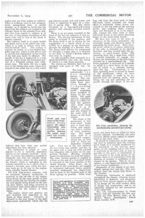
• The engine, clutch and gearbox are unit" mounted and supported in the
frame at 'three points. Attention is directed to: the neat design of the plain sheet-metal tuidershield, which fills the
gap between power unit and frame, and which is supported in place by a number of spring clips. The disc clutch transmits to a four-speed-and-reverse gearbox with centrally mounted control gear.•
There is an air pump mounted at the front of the box for purposes of tyre inflation. The driving mechanism of this pump is enclosed in the gearbox' and the pump itself is set in motion by the engagement of a clutch which is controlled, by a plunger on the dashboard, through the medium of a Bowden wire. The pump itielf delivers its compressed air through a copper pipe to a terminal on the dash, to which a flexible inflator tube -may be coupled.
An open propeller shaft transmits to a spiral-bevel-driven rear axle, the casing of which is a neat banjo pressing. , The wheels are Michelin discs and are equipped with tyres of 765 mm. by 105 mm.
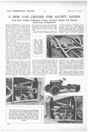
The brake gear is undoubtedly t h e most interesting, feature of this chassis. The centrally located handbrake lever opera t e s,, through a, c o mpen sating vvhipple tree, internal expanding sboes mounted in drums on the rear wheels. The pedal operates expanding shoes in a drum behind. the gearbox (this drum being ribbed so as to facilitate cooling), and also brakes of the same kind in drums on the front wheels.
The whole of the mechanism of this front-wheel brake gear is most interesting and ingenious, and is worthy of close examination. The pedal takes hold of a horizontal compensating bar, at both ends of which are dependent coupling rods. That one at the rear operates the foot brake cam spindle, and has, at its upper end, a wing nut with notched boss engaging with another on the supporting brac.kets, affording excellent means of adjustment for both the brakes. The other vertical spindle is coupled to a lever on the end of a cross-shaft which is mounted in the lower portion of the clutch housing. Other levers, one at each end of this cross-shaft, are to horizontal bell-crank levers suitably mounted underneath the dumb-irons, and as close to the forward ends of the front springs as possible. Other coup
Hag rods from the front ends of these bell-crank levers transmit the brake effort to horizontal brake levers ful-, crumed on the top ends of the steering pivots, and coupling links, screwed right and left-hand so as to be adjustable, connect the other arms of these bell-crank levers to the actual operating levers on the front-wheel brakes.
We have now come to the piece de resistance of the whole. mechanism, the extremely simple and effective means of expanding the brake shoes. Each steering pivot, which is, of course, stationary in the axle, is extended in an upward direction, and has, formed upon the extension, a quick-thread screw. The operating lever has a large boss, which is screwed internally to engage this thread, the mechanism in the boss being enclosed by a ease-hardened cap. The brake expander is mounted on a spindle on which is a short lever, at the outer end of which is a setscrew bearing upon this cap. Consequently, as the main operating lever is moved by means of the mechanism, which we have already, described, it tends to be unscrewed from the steering point, thus lifting the cap and operating the expander through the means of the set scretv and short lever to which we have already referred. Incidentally, the same setscrew affords ample means of adjustment as the shoes wear.
' It should be noted that, as the operating lever is mounted upon the steering pivot itself, it is entirely unaffected by the movement of the steering gear; again, as the coupling rod to this lever is anchored, at its front end, as near as possible to the point of attachment of the fore-end of the front spring of the chassis, there is no interference with the braking on account of oscillation of the chassis on its springs. This is, in our opinion, a very important feature which is not always considered. Suspension of the chassis is on semi elliptic springs fore and aft. The rear springs take the torque and thrust or the reaction.
Grease-gun lubrication is employed throughout the chassis, wherever grease lubrication is desirable, and altogether this new Unic chassis appears to embody in its design all the most modern ideas of design and construction, and to be admirably adapted for the conveyance of its rated load.
The sole concessionnaires in Great Britain and the Colonies for this new chassis are TJnic Motors, Ltd., of 18, Brewer Street, Buckingham Palace Road, London, S.W.