


A FRICTION-DR1VEN EIGHT-WHEELED CHASSIS.
Page 10
Page 11
If you've noticed an error in this article please click here to report it so we can fix it.
A Chassis which is Novel in its Reduction and Transmission Gear, and in the Mounting and Springing of its Four Trailer Wheels,
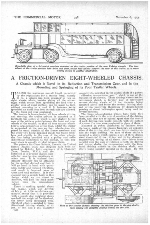
TAKING the maximum overall length permitted by the regulations for a tractor lorry., namely 33 ft. a vehicle has been designe&to run on eightwheels which, besides giving all the advantages which accrue from spreading the load over a
greater area of road surface; can be made to turn without reversing in a road 25 ft-. between kerbs (provided an extra four feet on each side are allowed for the front and rear ovei-hang).
The tractor is four-wheeled, all four wheels driving and steering, the trailer portion is mounted on a turntable the centre of which is only slightly to the rear of the midway point between the front and rear wheels of the tractor, so that all four tractor wheels bear a large proportion of the load, whilst the trailer is supported at the rear on four wheels—two disposed as usual outside of the frame members and the other two being disposed inside the frame members and slightly to the rear of the other wheels, the four being provided with a pulley and cable differential connection to the springs, so that any road shock is equally divided between them. The patents for Great Britain, Canada, the United States, France, Thal) and Belgium have been acquired by Rokeby. Ltd., engineers, of 5, Chancery Lane, London, W.C.2, and the intention is to produce chassis suitable for vans, lorries, omnibuses or other uses. It is claimed that greater efficiency can be attained by the method devised and that it Will go hand in hand with quietness, safety and reduced vibration, and result in lessened wear of tyres and road surfaces. It is also -claimed that a vehicle built to this design which we are about to describe, will hold the road much better than the conventional vehicle.
There is nothing special' about the engine, which will develop 45 b.h.p. at 1,000 -revolutions per minute, except that it is provided with a simple disc weighing about one-half the weight of rhe flywheel, the latter being dispensed with. Flywheel effect is assisted by three fibre-faced driving wheels, of 21 ins., 17 ins. and 9 ins. diameter
' n26 respectively, mounted on the central shaft of a patent " adhesion transmission gear " which is one of the features of the chassis. These driving wheels are for movements ahead, a further pair of fibre-faced reverse driving wheels of 12 ins, diameter being mounted above and below the central driving shaft and driven positively therefrom by double-helical gearing at about half-engine speed, being used for reverse motions.
The three ahead-driving wheels have their fihr-e faces parallel with the axis of rotation of the driving shaft, and they are so spaced apart that the centre of each driving face would coincide with the surfaee of a cone if a cone were employed in place of them. . Mounted in yokes (fulcrumed in Eirackets from the lower parts of the chassis framing), on opposite Bides of the driving shaft, are two driven shafts (inside the bogie -framing. On each of these shafts is mounted a sleeve which carries a set of three driven steel wheels (of 16 ins., 20 ins. and 28 ins, diameter respectively), having, at all times, their driven faces parallel with the axis of rotation of both the driving and driven shafts, for co-operation with the fibrefaced driving -wheels on the driving shaft, each sleeve being slidably spline "on its shaft. By this arrangement it is claimed that the formation cif " flats " on the fibre faces is rendered absolutely impossible. Also, as there is broad "line contact " right across the adhering faces of mating wheels, a highly and equally efficient balanced drive is obtained Oil all speeds.
The two off-side wheels are positively connected through double-reduction gearing with the driving shaft on the off side, whilst the near-side wheels are similarly connected with the driving shaft on the near side. In place of the double-reduction gear a single-reduction worm gearing may be oemployed if preferred.
Means are provided for holding sleeve-form intermediate thrust pieces in correct position on their shaft, whichever gear is in engagement. Gear changing is claimed to be effected with ease, silence and certainty by the depression of the " clutch " pedal. There is no actual, engagement or disengagement of clutch in the real sense of the word, as the action of the pedal is to move the driven shafts very slightly away from the driver shaft. The sleeves of the driven shafts are then moved from catch to catch by some simple mechanism which can be mounted on the steering column. There is nothing in the nature of a " gate " necessary.
In order to secure a differential action -when the vehicle is travelling on a curve, a balanced beam is arranged to be moved by the steering connections : spring pressure acting, on the beam is thus deflected and there is a rearrangement of the pressures between the driving fibre-faced and driven steel wheels with the result that less than one-half of the engine power is transmitted to the inner-driven shaft and more than one-half to the outer-driven shaft. This permits the two inner road wheels to travel at the slower speed required for curve negotiation:. The arrangement is designed to enable the two or three differential gears usually employed in fourwheel drives to be dispensed with, whilst racing of any wheelwhich loses contact with the road is pee' vented and all four wheels are in effect keyed together when travelling on the straight.
The aim in devising this adhesion gear is that it shall constitute a balanced clutch which subdivides the drive into four equal direct drives on all forward speeds whilst the vehicle is travelling on the straight, but will subdivide it in differing proportions correct to requirements when the vehicle is travelling on curves.
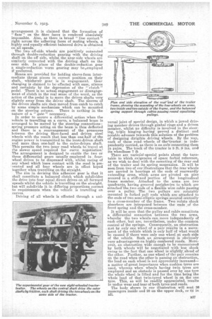
Driving of all wheels is effected through a uni versa' joint of special design, in which a jawed driving member drives through gimbal rings and a driven member, whilst no difficulty is involved in the steering, triple hinging having proved a distinct • and notable advance towards this solution of the problem of designing dirigible driving wheels. By the way, each of these road wheels of the'tractor is independently carried, as there is no axle connecting them in pairs. The track of the tractor is 5 ft. 9 ins, and its wheelbase 7 ft There are various special points about the turn table to which exigencies of space forbid reference, as we wish to deal with the mounting of the rear end of the trailer and its spring suspension. It will be seen from two of our illustrations that the rear wheels are carried in bearings at the ends of rearwardly extending arms, which arms are pivoted on pins scoured in a stiffened portion of the longitudinal frame member. Attached to the arms are two quadrants, having grooved peripheries to which are attached The two ends of aflexible wire cable passing over a pulley. The two pulleys are rotatably mounted in forked pull rods which are attached to the ends of two semi-elliptic springs secured centrally to a cross-member of the frame. Two volute shock absorbers are interposed between the ends of the front spring and the cross-member.
It will be seen that the pulley and cable constitute a. differential connection between the two arms, 'whereby the two wheels can move independently of each other, but are, nevertheless, under the common control of the springs. Consequently, an obstruction met by only one wheel of a pair results in a movement of the vehicle which is only half of what would be caused if there were only one wheel at each side of the vehicle. Such an arrangement is obviously very advantageous on highly cambered roads. Moreover, an obstruction wide enough to be encountered by both wheels will be negotiated with less shock owing to the fact that one wheel is slightly ahead the other. Further, as one wheel of the pair remains on the road when the other is passing an obstruction, the load on each wheel is not appreciably increased— a matter of great importance when cushion tyres are used, whereas when wheels having twin tyres are employed and an obstacle is passed over by one tyre the whole wheel is lifted and for the time being the whole load of that twin-tyred wheel is on the one tyre. This, as will be readily appreciated, results in undue wear and tear of both tyres and reads.
The body shown in our illustration will seat 26 passengers inside and 28 on the upper deck, or 64 in all.