


Nom Drivers &Mechanics
Page 22
Page 23
If you've noticed an error in this article please click here to report it so we can fix it.
Light Up Your Lamps At —
5.25 on Thurs. ; 5.23 on Fri. ; 3.21 on Sat. ; 5.18 on Mon. ; 5.16 on Tues. ; 5,14 on Wed.
Erecting Enbloc Cylinder Castings.
The sender of the following communication has been awarded the 10s. prize this week.
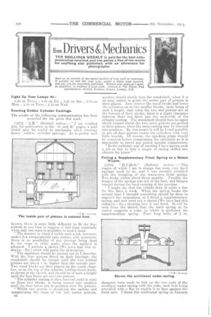
[1372] " A.H." (Bristol) writes :—"I ant sending you, for publication in the U. and M.' pages, a hint which may he useful to mechanics when erecting heavy enbloc ' cylinder castings. As is pretty well known, there is some little difficulty to fit the four pistons at one time in engines of this type, especially when only one mate is available to lend a hand.
" The manner in which I tackle such a job, however, makes it a comparatively easy matter,. and, moreover, there is no possibility of any damage being done to the rings or other parts when the methed is adopted. I enclose a sketch [We have had this redrawn.—En.] which will assist the description.
" The operation should be carried out as I describe. With the four pistons fitted on their bearings, the crankshaft should be turned until the two central pistons are about 1 in. -higher than the outside pair. Two wood blocks are then placed on the crank chamber, or on the top of the cylinder holding-down studs, as shown in the sketch, and should be of such a. height' until the four bores are over the pistons.
" The cylinder casting is then lowered until it rests on these two blocks, it being moved into position until the four bores are in position over the pistons. "Whilst one person is steadying the casting and compressing the rings of the two centre pistons, E4 another should slowly turn the crankshaft, when it. is an easy matter to guide the centre pair of pistons in their places. Now remove the wood blocks and lower the cylinders on to two smaller blocks, these being of such a height, that when the two end pistons are at the bottom. .of their stroke, there is a slight clearance between their top faces and the underside of the cylinder casting. The crankshaft should then be again slowly turned whilst the two outer pistons are guided to their places, when the main casting may be lowered into position. By this means it will be found possible to get all four pistons inside the cylinders with very little trouble. Of course, the sparking plugs should he removed before commencing the operation as it is impossible to insert any piston against compression. In the ordinary way of erecting I have known such a job as this to defy a couple of strong skilled mechanics for hours."
Fitting a Supplementary Front Spring to a Steam Wagon.
[1373] " II.J.McB." (Belfast) writes :—" The wagon of which I arn in charge has some very hard haulage work to do, and I was recently troubled with the breaking of the transverse front spring. Two broke within about three months. Possibly the temper of the springs, was not of the best, and fatigue ensued during the hard running of the machine.
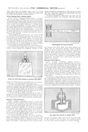
" I might say that the vehicle does 32 miles a day for five days a week. When the spring broke the second time I thought something should be done to improve the suspension, so I fitted a supplementary spring, and now send you a sketch [We have had this redrawn.—End showing how it was fixed. It will be seen from the sketch that the main spring at its centre supports a yoke, .to which is anchored the
supplementary spring. Four long bolts of in.
diameter were made to link up the two ends of the auxiliary under-spring with the yoke, each bolt being provided with a fiat to enable it to face against the front axle. I fitted this additional spring in January last, have had no trouble since, and am quite prepared for the rough work to which the vehicle will be subjected during the coming winter."
When Getting Gear Wheels Adrift.
[1374] " S.F.C." (Queen's Park) writes :—" I have come across many instances in which considerable damage has been done to the threaded ends of eardan shafts, live axles and spindles fitted with gear wheels when it has been found necessary to dismantle the gears during overhauling. In such eases the shafts have been merely placed on a couple of blocks and the threaded ends given several sharp blows with a hammer, in some cases with a sledge hammer, even, when the gear happens to have been an extra tight fit, the result being not only to distort the shaft but also to burr up the threads.
" This method, of course, is not one which would be adopted by a mechanic who has any respect at all for the part he is operating upon. When the time comes for these shafts to be erected it is found that the nuts will not pass on the damaged threads, and the shaft has either to be put in the lathe and have new threads cut, or some attempt is made at filing up the threads to permit the fitting of the nut.
" The sketch I send you [We have had this redrawn. —En.] shows a most simple way of getting gear wheels adrift without doing the slightest damage to the
.hafts on .which they are mounted, and the method, if adopted, will save much time and trouble. " A part of the necessary equipment consists of an ordinary swage-block, obtainable from most secondhand tool dealers, and the tool required to dislodge the seized-up gear is made out of a piece of bar steel of about 1., in. diameter and 7 in. long, bored out at one end to a depth of about qinches.
"To get the gear adrift, one end of the shaft is placed in a. hole in the swage-block and the heaviest of blows can be applied without any damage whatever being done to the shaft, thre-ads, or gearwheel."
Making a Fibre Hammer.
[1375] " A.Ff.H." (Llandaff) writes :—" I got dissatisfied with the ordinary form of lead hammer which we used in our repair shop, the lead breaking away in pieces after the hammer had been in use a little while. I decided therefore to construct a hammer having fibre faces, and it proved to be mostadurable. I found it very useful when fitting such pelts as bushes, thrust-rings, fixing into place new porcelain or soa.pstones for ignition plugs, driving fibre gears into position and other delicate parts.
" I send you sketch [We have had this redrawn.— ED.] showing the construction of the hammer. To make it I obtained a piece of aluminium tubing about
in. bore, and cut this to a suitable length to form part of the bead. A few holes 3-16 in. diameter were drilled around its circumference, and lead poured into the tube, which also entered the small holes and was thus held firmly in position.
" I then recessed the lead back into each end of the tube for about 1 in. in depth. For the faces of the hammer two fibre plugs were then turned and fitted into the aluminium tubing. Each of these should be fixed in position by means of a, couple of small set. screws as shown in the sketch. Of course, both the fibre plugs should be a driving fit in the aluminium tubing. That part of the barrel containing the lead is then drilled to accommodate a suitablasshaft. The fibre faces, when worn, can be replaced very readily."
Refacing Valve Seats.
[13761 " A.A.W." (Waltham Abbey) writes :— " Drivers of steam wagons sometimes find it necessary to reface the seatings of the water-delivery and check valves which are fitted on their machines. To do this generally means either replacement for the time being, or the valve has to be taken adrift from the vehicle in order to effect the repair. This means a. considerable amount of unnecessary delay, and I myself consider that it should be possible always to do a job without breaking up the pipe-line to take the valve down.
"I send you a sketch [We have had this redrawn.— En.] showing how this is effected. I have made a rosebit, accommodated with a squared end to fit an engineer's brace or spanner, a brace, of course, being the most effective. The cap of the valve-body is taken off and replaced by a plug suitably screwed and bored out to act as a guide for the stem of the rosebit. A fairly strong coil spring, which will just fit over the stem of the rosebit, is an advantage, as it helps to keep the bit square and hard against the valve seating.