


USEFUL GARAGE TOOLS AND APPLIANCES.
Page 33
If you've noticed an error in this article please click here to report it so we can fix it.
Wheel-drawing Tools and Other Equipment Devised by our Driver and Mechanic Readers.
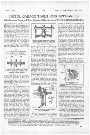
SIMPLE, cheap, mid efficient wheel-L-1 drawer has been designed by— a mechanic, and the sketch, with covering note, sent to us by his employers for publication on this page. We are giving this sketch the premier position this; 'week, because, in our opinion, it merits It; the prize money we shall, of course, award to the mechanic who was responsible for the design.
The tool is so simple in design that a description of it is hardly needed. It consists simply of a piece of 1-in by 0.n. flat steel bar, bent in the form of a very narrow, tall U. The apace between the legs of the -U. is just sufficient to accommodate the two setscrews 'which are used to apply the pull necessary to withdraw the wheel. In the
case of solid wheels it will be necessary to drill and tap holes in the web to accommodate the screws. Wheels which have arms or holes already in the web will be helped out by the provision of Suitable packing washap or strips of bar iron backed by nuts, into which the Oetscrews will engage.
HEAVIER and more substantial altogether is the tool designed by of -Lanark.Its chief pus.pose is to facilitate the withdrawal of the sprocket -pinions. of . chaiii-driyen . Chassis, an operation which is, more Often than not, attended with a. ConSidera,ble amount of • trouble; :as .many enerienced readers will agree. Two 'creashars, of in. by Steel; are' Selected, of sufficient length to enable • the tool to cope with the largest size 'sprocket with -which. the niechanic-antiCipate.s he Will have to deal... They-are bolted together, near their ends, as shown on the sketch, With distanc6 Pieces PT in thick intervening. The • hooks are made from 1-in, bar steel, ferged to shape at the'erids, -and serewed a Whitworth thread for the realer portion of their lengths. They are equipped . -with nuts and washers. which Will con'venientiv. bear on the upper surface of the crossbars. The central belt shoUld be about a foot long, and it, tOo, has a
nut-and washer similar to those on the hooks. The nut and washer are indicated in the sketch by the letters A and D respectively; E is a supplementary washer td serve as a packing piece between B, which is the nut on the end of the sprocket shaft, and the nut (A).
The mode of operation, as outlined by
" in his letter, is rather ingenious if, perhaps, unnecessarily complicated. The hooks and centre bolt are first adjusted an that, whenthe fernier embrace the rim of the sprocket, the end of the bolt engages the end of the
• 'sprocket shaft. •The nut (B) is then slacked hack Clear of the sprocket and made to bear against the washer (E), which itself is in close contact with A. The central bolt is then manipulated to withdraw the sprocket, end, after the .latter has moved a little, and providing it is not immediately freed, additional pressure may be applied (a) by use of the nut (B), and (h) by screwing down • the nuts on the hooks. •
The same appliance can be used for withdrawing wheels, if suitable backing plates be used in conjunction With the hooks, so that the plates bear against the spokes of the wheel, and the hooks make contact with the plates.
. . •
• A USEFUL addition to the ordinary garage equipment is a grindstone. As a rule, when one is provided it is hand-operated, which is hardly con
vement, it it has to be utilized by one man, since, as a general rule, two hands are required to hold the tool which is to be ground, that is, if the grinding is to be done properly. " F.W.H.," of Manchester, sends a sketch and brief description of a treadle applied to such a tool. • The handle is removed, and a hole drilled in the crank-arm, about 2 ins. from the centre. A simple crank-pin is then made, which can be secured in the arm by a couple of nuts as Shown. The treadle is a plain piece of wood, mounted on a. pin secured to the leg of the bench, whilst the connecting rod is a piece of hard wood bushed at each end.
It may be worth while to note that the need for a second hole in the crankarm is brought about by the fact that, if the crank-pin were to be fitted into the hole occupied by the handle, the movement of the connecting rod would be excessive and inconvenient. Placing the Din nearer the centre reduces that movement.
TROUBLE appears to have been experienced by " S.F.V.," of Kensington owing to badly dressed cylinder castings. At any rate, he has found it to be necessary to scrape-the insides of the combUstion heads in order to remove ridges left there, the said ridges being . . sufficient, in some cases, to cause pre . ignition, to which he refers as "top • knoCk."
To remove these ridges he uses along round filespoonshaped at the end, aa shown in 'the, sketch, to form a scraper. To facilitate operations he employs a simple bracket or support forthe scraper. -This bracket is simply a piece of mild steel bar, about a in, by in., or
• Lin. by 4 in'; the exact dimensions do not matter. 'This•bar is slottedat one end, so that it can be held in the cybrider_ by,means of one of the cylinder feet bolts. The other end is .drilled to accommodate the file, which rests in it and • is fulcrumed on it. s