


Patents Completed.
Page 22
If you've noticed an error in this article please click here to report it so we can fix it.
Complete specifications of the following patents will be sent to any address in the United Kingdom upon receipt of eightpence per copy at Sales Branch, Patent Office, Holborn, W.C.
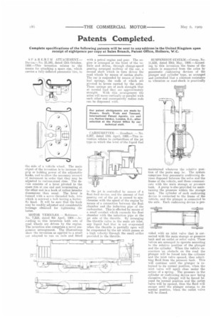
SPAR E-R I M ATTACHMENT.— Davies.-----No. 21,541, dated 12th October, I908.—This invention relates to the means for attaching a spare rim, which carries a fully-inflated pneumatic tire, to
theside of a vehicle wheel. The main object of the invention is to increase the grip or holding power of the adjustable hooks, and to allow the necessary amount of movement in order that they may be adjusted to various-sized rims. The device consists of a lever pivoted to the spare rim at one end and terminating at the other end in.a hook of rather broader dimensions than usual. The lever is formed with a screw-threaded hole, into which is screwed a bolt having a butterfly head. It will be seen that the hook may be readily adjusted and considerable leverage obtained for tightening the latter
MOTOR VEHICLES. — Robinsen. — No. 7,510, dated 4th April, MS.—According to this invention both sets of road wheels are driven by the engine. The invention also comprises a novel suspension arrangement. The illustrations show the invention as applied to a small ear adapted to run on rails and fitted with a petrol engine and gear. The engine is arranged at the front of the vehicle and drives, through change-speed gearing arranged midway of the ear, a second shaft which in turn drives the road wheels by means of carder). shafts. The car is suspended by means of heavy leaf springs, the ends of which are pivoted to levers carried by the axles. These springs are of such strength that at normal load they are approximately straight. With this arrangement the axles will move vertically or parallel with each other and consequently radius rods can be dispensed with.
CARBURETTER. — Goodhart. — No 8,007, dated 10th April, 1908.—This in vention relates to carburetters of the jet type in which the level of the liquid fuel in the jet is controlled by means of a float-feed device, and the amount of fuel passing out. of the jet is caused to synchronise with the speed of the engine by means of a connection between the float chamber and the induction pipe of the carburetter, This is effected by means of a small conduit which connects the float chamber with the induction pipe at the jet side of the throttle. By arranging the throttle valve in the main air inlet, any liquid fuel that is not evaporated when the throttle is partially open will be evaporated by the air which passes at a high velocity through the small orifice provided in the throttle.
SUSPENSION SY STEM.—Cowey, No. 11,658, dated 29th May, 1908.—According to this invention the frame of the vehicle is supported from the axles by pneumatic cushioning devices of the plunger and cylinder type, so arranged and controlled that a constant resistance to vibration or road-shock is practically maintained whatever the relative position of the parts may be. The system comprises four pneumatic cushioning devices disposed between the axles and the frame of the vehicle, and these communicate with the main storage or pressure tank. A pump is also provided for maintaining the pressure within the storage tank. The cylinder of each cushioning device is connected to the frame of the vehicle, and the plunger is connected to the axle. Each cushioning device is pro
vided with an inlet valve that is connected with the main storage or pressure tank and an outlet or relief valve. These valves are arranged to operate according to the relative position of the plunger and the cylinder. When the vehicle encounters an obstacle on the road the plunger will he forced into the cylinder and the inlet valve opened, thus admitting fluid from the pressure tank. This will continue until the plunger is returned to its normal position, when the inlet valve will again close under the action of a spring. The pressure in the cylinder or cushioning device now being excessive, the plunger will be forced beyond its normal position and the outlet valve will be opened, thus the fluid will escape until the plunger returns to its normal position, when the outlet valve will be closed.