


Overhead Camshaft Valve Adjustment
Page 82
If you've noticed an error in this article please click here to report it so we can fix it.
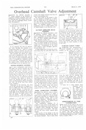
pATENT No. 807,927 describes a 1" simple solution to the problem of adjusting overhead camshaft valve gear (l. Weaving and The Austin Motor Co.. Ltd., both of Longbridge Works, Northfield, Birmingham.)
In the drawing, the cam (1) operates the valve through the medium of a compression piece (2). This is a conical member which, if moved, can vary the clearance between the cam and the valve.
This provides the means for adjustment and is regulated by a pair of locknuts (3) on the tail of the cone. As the cone must of course reciprocate with the valve it is located by a spherical seating at the point (4). A spring (5), bearing on the support pillar, ensures that the unit is held firmly on to its spherical seat.
POWER STEERING CONTROL
ALL servo mechanisms must have a slight lost motion between the first moving part and the control valve in order that they may "stay put S' in any position. In a steering system, this lost motion may be taken up by road shocks and the. servo motor put to a lot of unnecessary work. A connection claimed to overcome this defect is shown in patent No. 807,854 (W. Kirk, H. Flewellen and Westinghouse Brake and Signal Co., Ltd., all of 82 York Way, King's Cross, London.)
Referring to the drawing, the drop arm of the steering box is coupled to a ball (1) whilst the other ball (2) works the steering linkage_ A main lever (3) is pivoted on a fixed point off thc lefthand edge of the drawing and a control lever (4) works the fluid control valve, also not shown. The two levers are joined on the pin (5) but are permitted a certain lost motion between the boss (6) and its surrounding bore.
The main point of the patent is that the lost motion is damped by a rubber bush (7) which has to be compressed on one side before any relative movement can occur, so that minor shocks have no effect, A modified scheme is shown employing a pair of rubber blocks each of which damps in one direction only.
SUCTION OPERATED ROAD SWEEPER
PATENT No. 808,026 describes a road sweeping machine which uses a suction technique to eliminate airborne dust. (Deighton's Patent Flue and Tube Co., Ltd., and L. Riddell, both of Pepper Road, Hurtslet, Leeds, 10.)
The drawing shows the machine in outline: it is small enough to be steered by a tiller (1) and is driven by an air-cooled engine (2). Transmission to the small road wheels is taken through a gearbox (3) and chains, (4).
A right-angled belt (5) from the crankshaft drives the fan and other belts and chains rotate the main horizontal brush (6) and a vertical gutter brush (7). The dust-collecting box (8) is kept at below atmospheric pressure by the fan (9) and so is the whole brush enclosure, the only air inlet being between a pair of valances (10). By this means all dust raised by sweeping is sucked inside and cannot form external clouds. The vehicle is stated to be 74 ft. long and 44 ft. wide.
SWIRL COMBUSTION CHAMBER
PATENT No. 807,712 refers to directinjection oil engines in which a rotary swirl is imparted to the air charge. The patent describes an improved combustion chamber design, said to give improved efficiency. (Ricardo and Co. Engineers (1927), Ltd., 21 Suffolk Street, Pall Mall, London, S.W.1.)
The combustion chamber (1) is situated in the crown of the piston and in the case illustrated consists mainly of a separate insert, although the conical nose (2) is part of the piston. The injector (3) has four evenly spaced spray nozzles.
The novelty of the design is the use of four projections (44, from the Wall of the conical chamber. Seen in ri.an, these projections are of saw-tooth outline and the direction of the air swirl is up the slope of the teeth. As the compressed air passes over the edges of the teeth, four local eddies are created; these revolve on top of the general swirl and gise added turbulence. Another scheme shows the chamber with only one projecting edge; no insert member is used in this case.
TUBELESS SAFETY TYRES
A TUBELESS tyre incorporating a r-Vsecond chamber to prevent total collapse in the event of a burst is described in patent No. 808,481. The tyre is said to be suitable for both aircraft and road vehicles. (Dunlop Rubber Co., Ltd. i 1 --Albany, Street, London, N.W.1-)
The drawing shows a cross-section of the proposed tyre. The cords of the outer wall arc so constructed that they constrict inwards upon inflation and so form a tight seal on the rim. A second and smaller tyre is placed inside, located from the outer' one by spacing rings attached to the smaller tyre. The tyre shown is intended for carrier-based aircraft and is inflated to 100 lb. sq. in. in the large chamber and 200 in the smaller one, thus requiring two separate valves.
If made for a road vehicle, both chambers would be inflated to the same pressure and would employ a common valve. A restriction would be included, however. between the two compartments.
IMPROVEMENTS IN TYRE CONSTRUCTION
THE layout of the cords in the carcass of tyres forms the subject of patent No. 808,341. The cords are wound on a former and cross at an angle of from 20 to 30 degrees. The cords may be made of cotton, silk, flax, rayon, nylon, Terylene or steel wire. The patent'comek from Dunlop Rubber Co., Ltd.,•1 Albany Street, London. N.W.1. r