


Patents Completed,
Page 24
If you've noticed an error in this article please click here to report it so we can fix it.
Complete specifications of the following patents will be sent to any address in the United Kingdom by the Sale Branch, Patent Office, Holborn, W.C., upon receipt of eightpence per copy.
A New Drill Socket.
J. E. Morrow, No. 23,293, dated Ilth October, 1912.—This drill socket is of the ordinary general form, but the taper portion is spirally slotted so as to leave a helical resilient portion extending to the open end of the drill socket. This portion cart extend diametrically, and at the same time can contract longitudinally so as to allow the easy insertion of a
drill. When the socket is in Use the resilient portion tends to bind upon the drill and to lock it in position.
Resold Chain Improvements.
C. G. RenoId and Hans Renold, Ltd., No. 3888, dated 16th February, 1912.— This invention relates to silent chains of the type in which a guide link is arranged to project into a groove in the chain wheel, or to overlap the sides of the teeth, so as to prevent lateral displacement of the chain when running. The object of the invention is to render the various units of the chain of equal elas ticity and strength. The guide links are made of such a material that, although of a different section, they have the same elasticity and strength as the tooth links, and therefore take their fair share of the load. By this means, the load is uniformly distributed over the maximum surface available on the studs, and the chains may be rated for a higher load. When guide links are used on each side of the chain, they are made of about half the thickness of ordinary links, so that the total strength of the unit of a chain having guide links, is the same as that of a unit net :laving these fittings.
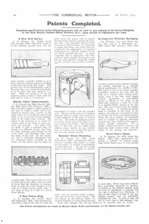
A New Piston Ring.
A. G. Ionides, No. 21,371, dated 19th September, 1912.—This specification describes a ring of the type in which the gases above the piston tend to expand the ring and to press it against the cylinder wall. The particular feature of the invention is the provision of a ring that is simple and cheap, and which does not necessitate the employment of separate bridge-pieces to prevent leakage of the gas which expands the ring. A single composite ring is employed; this comprises an inner member of L-section, and also an outer member which fits within the first member and provides a continu ous surface in contact with the cylinder wall. The face of the piston is of smaller diameter than its trunk, and a groove is formed adjacent to the head to receive the ring. The ordinary passages to allow the access of the gas to the back of the piston ring are provided. The two members of the ring can be locked from relative rotary motion by any suitable form of locking pin, so that the gaps in the two rings cannot coincide.
Sprocket Wheel Mounting.'
G. E. Forster, No. 7501, dated 27th March, 1912.—According to this inventinn, a pulley, belt sheave, or other driving sleeve, is divided longitudinally on the centre line. On one, or on both ends is provided a thread of suitable
pitch, and die sprocket wheel is internally screwed to lit on this thread. The two halves of the driving sleeve are secured together by a bolt passed through them and through the driving shaft An Improved Wolseley Springing.
The Wolseley Tool and Motor Car Co., Ltd., and A. A. Remington, No. 1886, dated 24th January, 1912.—This
invention relates to the method of springing already described in a previous patent specification No. 16,879, of 1911. The object in view is to secure a quicker periodicity between the axle and the body of a vehicle under rolling movements, than is the case under simple vertical movements. A semi-elliptic springis affixed to the frame at its front end; junction is made by a link to a, quarter-elliptic spring at its rear end. The axle is hung from the middle
of this spring. A transverse-rocking shaft is mounted on the frame of the chassis, and arms are connected by links to the free end of the semi-elliptic spring. When the van is rolling, the transverse shaft is twisted in opposite directions at each end, thus rendering the quarter• elliptic springs inoperative. For a simple vertical movement, however, the transverse shaft rotates freely, and the whole of the springs are operative.
Novel Piston Rings.
H. H. Patrick, No. 6973. dated 21st March, 1912.—This specification deacribes a method of making piston rings which have a pair of coils parallel to each other. These rings have hitherto been somewhat expensive to produce. According to the present method, great accuracy of machining is possible, and the coat is reduced to a minimum. A pair of steel rings is formed in any convenient manner, and are preferably machined all over. A piece is then cut out of each ring in the ordinary way, .and the opposite ends are welded.