


From Drivers and Mechanics.
Page 23
If you've noticed an error in this article please click here to report it so we can fix it.
When Mending Canvas Hose.
[1234] " W.S." (Leyland) writes -" I do not know whether the drivers of fire engines are in the habit of reading TuE COMMERCIAL MOTOR, but I can say that many of the fitters employed at works where fireengines are made do read your journal. I hope that the following little hint on the repair of canvas hose pipes will be of interest.
"The most important tool required for the job is a small east-iron anvil, specially constructed to fit inside the pipe. I am sending you a sketch—[We have had this redrawn.—En.] in order to make my meaning clearer. In addition to the anvil, the materials required for mending a small hole consist of a Ain. copper rivet I in. in .length, two leather washers 21in. diameter and a !copper washer to suit the rivet.
" The repair is effected as follows. The anvil is warmed slightly, and just a little melted resin is poured on to the hollowed-out portion. The rivet. head downwards, should then be stuck on to this place, and the leather washer placed over the shank. The anvil with the washer and rivet in position is next placed in the end of the hose, and is allowed to slide down until it is approximately opposite to the hole, which has been previously marked. The end of the rivet is then worked about, until it projects some little distance through the hole. It is then gripped with a pair of pliers and broken from the anvil. The hose is next. placed flat on the floor, and the other leather is placed over the rivet, of course on the outside of the pipe, and the copper washer is placed over it and the whole lot riveted together. I have repaired several leaks in this way, and have found them last until the hose has been finally scrapped. The sketch also shows the riveting tool which is used." When Facing Up Valves.
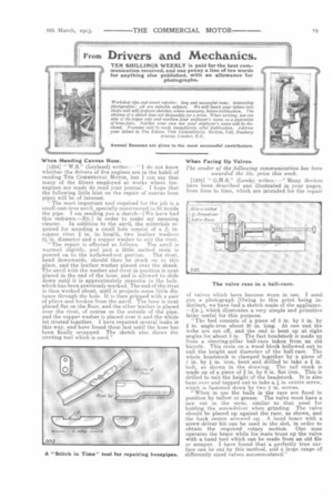
The sender of the following communication has been awarded the Ws. prize this week.
[1235] " G.H.S." (Leeds) writes :—" Many devices have been described and illustrated in your pages, from time to time which are intended for the repair of valves which have become worn in use. I send you a photograph [Owing to this print being indistinct, we have had a sketch made of the appliance-End, which illustrates a, very simple and primitive lathe useful for this purpose.
"The bed consists of a piece of 3 in. by 3 in. by -1 in. angle-iron about 20 in. long. At one end the webs are cut off, and the end is bent up at right angles for about 3 in. The fast headstock is made up from a steering-pillar ball-race taken from an old bicycle. This rests on a wood block hollowed out to suit the height and diameter of the ball-race. The whole headstock is clamped together by a piece of 1 in. by in. iron, bent and drilled to take a in. bolt, as shown in the drawing. The tail stock is made up of a piece of in. by 9 in. flat iron. This is drilled to suit the height of the headstock. It is also. bent over and tapped out to take a in. centre screw, which is fastened down by two 3 in. screws.
"When in use the balls in the race are fixed in position by tallow or grease. The valve must have a saw cut in the stem, similar to that used for holding the screwdriver when grinding. The valve should be placed up against the race, as shown, and the back centre screwed up. A hand brace with a screw-driver bit can be used in the slot, in order to obtain the required rotary motion. One man operates the brace while his mate trues up the valvewith a hand tool which can be made from an old file or scraper. I have found that a perfectly true surface can be cut by this method, and a large range of differently sized valves accommodated."