


A Magnetically Operated Gear
Page 68
If you've noticed an error in this article please click here to report it so we can fix it.
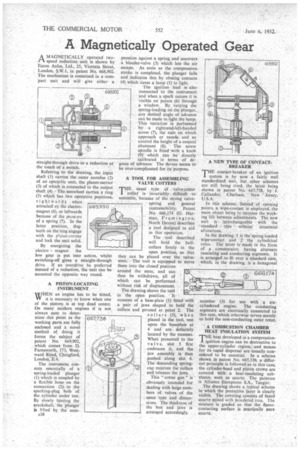
AMAGNETICALLY operated twospeed reduction unit is shown by Eaton Axles, Ltd., 25, Victoria Street, London, S.W.1, in patent No. 668,902. The mechanism is contained in a compact unit and will give either a
straight-through drive or a reduction at the touch of a switch, ' Referring to the drawing, the input shaft (1) carries the• outer annulus (2) of an cpicyclic unit, the planet-carrier (3) of .which is connected to the output shaft (4). The sunwheel carries a ring (5) which has two operative positions, rightwards .when attracted oy the electromagnet (6), or leftwards because of the pressure of a spring (7). In the latter position, dogteeth on the ring engage with the planet-csrrier and lock the unit solid.
By energizing the
-electro magnet the low gear is put into action, whilst switching-off gives a straight-through drive. If an overdrive be preferred instead of a reduction, the unit can be mounted the opposite way round.
665330 , A PISTON-LOCATING INSTRUMENT
WHEN an engine has to be timed, it is necessary to know when one of the pistons is at top dead centre. On many modern engines it is not always easy to determine this point as the working parts are fully enclosed and a novel method of doing it forms the subject of patent No. 669,902, which comes from D. Farnsworth, 173, Westward Road, Chingford, London, E.4.
The instrument consists essentially of a spring-loaded plunger (1) which is coupled by a flexible hose on the connection (2) to the sparking-plug hole of the cylinder under test. By slowly turning the crankshaft, the plunger Is lifted by the corn A38 pression against a spring and uncovers a bleeder-valve (3) which leis the air escape. As soon as the compression stroke is completed, the plunger falls and indicates this by closing contacts (4) which cause a lamp (5) to light.
The ignition lead is also connected to the instrument and when a spark occurs it is visible on points (6) through a window. By varying the spring-loading on the plunger, any desired angle of advance can be made to light the lamp. This variation is performed by a rightLand-left-handed screw (7), the nuts on which approach or recede and so • control the height of a conical abutment (8). The screw spindle is fitted with a knob (9) which can be directly calibrated in terms of degrees of advance. The device seems to be over-complicated for its purpose.
'A TOOL FOR ASSEMBLING VALVE COTTERS 'THE usual type : of valve-cotter I collar is invariably • difficult to assemble, because of the strong valve
spring and • general inaccessibility. Patent No. 666,174 (c. Harman, Freinington, North Devon) describes a tool designed to .aid in this operation.
The tool described will hold the halfcollars firmly in , the open position, so that they can be placed over the valvestem. The tool is equipped to move them into the closed position around the stem, and can then be withdrawn, all of which can be performed without risk of displacement. The drawing shows the tool in the open position. It consists of a base-plate (1) fitted with a pair of jaws shaped to hold the collars and pivoted at point 2. The collars (3), when placed in the tool, rest upon the baseplate at 4 and are definitely located by the recesses. When presented to the valve, slot 5 first embraces it, and the jaw assembly is then pushed along slot 6. The descending spring. cup receives the collars and releases the jaws.
This "cotter gun" is ' obviously intended for dealing with large numbers of valves of the same type and dimensions. The thickness of the box and jaws is arranged accordingly. A NEW TYPE OF CONTACT'BREAKER
THE contact-breaker of an ignition system is by now a fairly well standardized unit, but other schemes are still being tried, the latest being shown in patent No. 667,738, by J. Callander, Chatham, New Jersey, U.S.A.
In this scheme, Instead of opening points, a wipe-contact is employed, the main object being to increase the working life between adjustments. The new Unit is interchangeable with the • standard type without structural alterations.
In the drawing,•1 is the Spring-loaded wipe-contact and 2 , the cylindrical rotor. The latter is made in the form of a commutator, having alternate insulating and conducting segments. It is arranged to 'fit over a standard cam, which, in the drawing, is a hexagonal
member (3) for use with a sixcylindered engine. The conducting segments are electrically connected to this cam, which otherwise serves merely to hold the non-conducting outer rotor.
A COMBUSTION CHAMBER HEAT INSULATION SYSTEM THE heat developed in a compression1 ignition engine can be destructive to the upper-cylinder region, and means for its rapid dispersal are usually considered to be essential. In a scheme shown in patent No. 665,330, a different principle is followed as in this case, the cylinder-head and piston crown are covered with a heat-insulating substance, such as quartz. The patentee is Alliance Europeene S.A., Tangier.
The drawing shows a typical scheme in which the protective layer is clearly visible. The covering consists of fused quartz mixed with powdered iron. The mixture is graded so that the flamer contacting surface is practically pure quartz.