


Differential Gear with a Damped Action
Page 52
If you've noticed an error in this article please click here to report it so we can fix it.
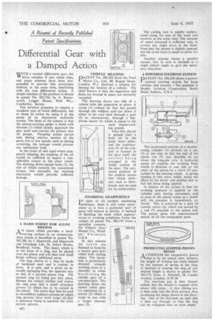
MUITH a normal differential gear, the VII drive vanishes if one wheel slips, and many schemes have been propounded to prevent this occurrence without, at the same time, interfering with the true differential action. A simple solution of the problem is shown in patent No. 585,736, by A. Butterworth, Logger House, Park Wai, Camberley, Surrey.
This inventor proposes to employ a standard type of bevel differential, but to damp its action by using it as the pump of an obstructed hydraulic system. The basis. of the scheme is that the pinion-carrying spider is fitted with shrouds (1) which closely approach the gear teeth and convert the pinions into oil pumps. Pumping action occurs only during relative motion of the parts, but at low speeds, such as during cornering, the leakage would prevent any substantial load.
In the event of one road wheel completely slipping, the trapping of the oil would be sufficient to impart a considerable torque to the other wheel. The drawing shows escape holes (2), the size of which controls the transmitted torque, but normally the working clearances would provide sufficient leakage.
A HARD INSERT FOR ALLOY PISTONS
AN insert which provides a hardwearing surface in an aluminiumalloy piston is described in patent No. 585,284, by J. Hepworth, and Hepworth and Grandage Ltd., St. John's Works, Bradford, Yorks, The insert, which is in the form of a ring, can be placed over the piston and will then lock itself firmly without additional parts.
'The ring, shown at 1, may be made of hardened steel and is conical in form. It is split, and is given an inwardly springing bias, the opposite way to that of a normal piston ring. The normal ring (2) being put into place, flattens the conical outline and makes the ring snap into a small extension groove (3) which. has to be turned in the piston:. The insert may also be used to recondition ordinary.,pistons cif which ring grooves have worn large, all. __that is necessary being to machine the extra narrow groove.
VEHICLE HEATING
PATENT No. 585,303 from the Ford Motor Co., Ltd., 88, Regent Street, London, W.1, discloses a scheme for heating the interior of a vehicle. The chief feature is that the apparatus and ducts are housed in space not normally occupied.
The drawing shows one side of a vehicle with the apparatus in place. A scoop (1) collects air that has passed through the radiator and can direct it either in the cool state through a port (2) or, alternatively, through a fan driven heater (3) which is piped to the
main engine-cool ing system.
After this, the air is passed into a bore (4) in the main door pillar, and the continuation (5) of the conduit is formed in the door itself, the outlets being arranged in the inside surface of the door. The protected position of the conduit means that cheap material, such as fibreboard, may be used for its construction.
FINISHING GEARWHEELS 1 N spite of all modern machining &technique, there is still some uncertainty as to how a particular pair of gears will behave in service. A method of finishing the teeth which approximates to working conditions forms the subject of patent No 586,193 from a specialist concern, the Fellows Gear .586.m Shaper Co., Windsor, Vermont, U.S.A.
In this scheme the teeth are finished to form by a master gear provided with cutting edges. The invention is particularly directed towards working close to a shoulder as when machining the smaller gear of a one-piece pair. The drawing shows the master cutter gear (1) operating on a pinion (2) which is made in one with a larger . internal gear (3). The cutting tool is rapidly recipro cated along the axis of the work and 'evolves at the same time. The arnouni of metal removed is sufficient only to correct any slight error in the form Note that the master is slightly tapered, but the tooth form is made to allow for this.
Another scheme shows a parallel master, but its axis is inclined at a slight helical angle to give the neeessary clearance.
A POWERED STEERING SYSTEM
PATENT No. 586,206 Shows a powerassisted steering system for large vehicles and tractors. The patentee is Bendix Aviation Corporation, South Bend, Indiana, U.S A.
The mechanism consists of a doubleacting cylinder (I) pivoted on a pin (2) at one end, so that the end of the piston rod (3) may describe an arc about the king-pin axis. A hydraulic pump (4) supplies the working fluid, which is directed to one side or the other of the piston by a valve (5) controlled by the steering wheel. A spring loading in this valve mildly resists the effort of the driver and enables him to feel the force being applied.
A feature of the system is that the working pressure is applied to the cylinder only during movement, and as soon as the piston comes to a standstill, the pressure is immediately relieved. This is achieved by a pair of control valves (6), which are moved by a rod (7) attached to the piston rod. The patent gives full constructional details of all the component parts.
PRODUCING STEPPED PISTON RINGS
A LTHOUGEL the stepped-slot piston I—&ring is by no means new, hitherto the length of overlap has been limited by the amount of spring in the ring. A method of making the step _of any desired length is shown in patent No. 585,375, from A. Mitchell, 28, Linden Avenue, London, N.W.10.
The cast-iron pot is first threadmilled, but the thread is stopped after about lath turns. A thin slitting saw is then sunk into the thick portion, thus producing the shape shown in the drawing. One of the slot-ends on each side is then cut through so that the ring can be collapsed into an even depth.